2 - 58
SPEC
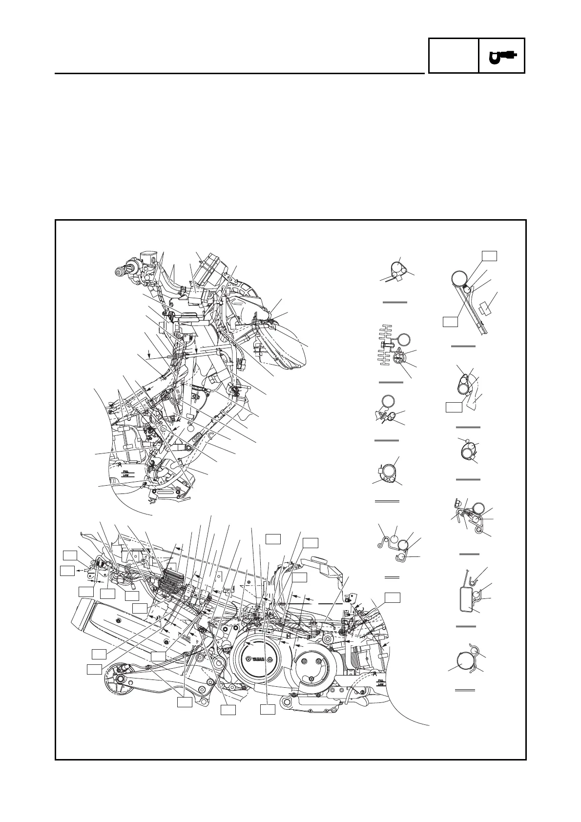
CABLE ROUTING
È After adjusting the adjustment nut, attach the
front and rear parts of the boot tightly.
É Pass the seat lock cable between wire harness
and frame.
Ê Connect the wire harness (wire taped area) to
the T stud of frame.
Ë Fasten the cooling system air bleed hose and
rear brake lock lever cable together with the
plastic clip. The open ends of the clip should
face downward.
Ì Route the main switch lead in front of the ignition
coil bracket, then to the outside of the frame.
Í Fasten the wire harness, main switch lead, and
seat lock cable with the plastic band under the
stay 1. Be sure to fasten the seat lock cable on
the metal section of the outer cable.
Î Pass the main switch lead between stay 1 and
seat lock cable.
Ï Fasten the wire harness and ECU (engine) lead
to the stay 1 with a holder.
Ð
Ñ
Ò
A-A
B-B
D-D
F-F
J-J
K-K
H-H
C-C
E-E
G-G
I-I
P
P
C
B
O
Q
D
R
T
D
D
T
P
U
U
U
P
U
V
S
W
N
X
P
Q
Q
N
A
A
B
B
B
9
8
7
Ó
Ô
Õ
Ö
Ï
6
5
2
1
Î
Í
Ì
Ë
Ê
É
È
AR
AD
AC
AG
AA
AL
AJ
AN
AE
AS
S
M
N
Y
U
U
Q
P
P
P
Q
U
K
J
J
I
H
H
C
D
D
G
G
E
E
F
F
C
I
K
Ø
Ù
Ú
Û
Ü
D
E
G
F
H
I
À
ß
Ý
Þ
Ý
AI
N
L
K
J
C
×
4
3
0
A
M
AF
AO
AP
AM
AB
Á
AH
AK
AQ



 To Next Page