7
2. PRE-OPERATION PROCEDURES
Installation Procedures
Warning
10. Connect to adequate power source.
Be sure unit is connected to a sufficiently
rated power source (see table to right).
Type Power Source
Capacity
SM201
AC115V
single-phase
13A or more
SM301
AC115V
single-phase
15A or more
SM311
AC220V
single-phase
9.5A or more
SM501
AC115V
single-phase
15A or more
SM511
AC220V
single-phase
9.5A or more
11.
Observe wire color designation.
Confim that the facility main breaker is OFF before
connecting the round terminals from the power cable. No
power plugs or connectors of any kind are included with
CF series units. Where required, purchase an appropriate
plug and properly connect using the round terminals (see
table to right).
Wire color Facility terminal
Black Live side
White Neutral side
Green Ground
12. Connect power cable.
Confirm main power switch is turned off prior to connecting the power cord. SM311 and 511 models
do not include plugs. Select a power connection device (i.e. plug) appriate to rating and power source.
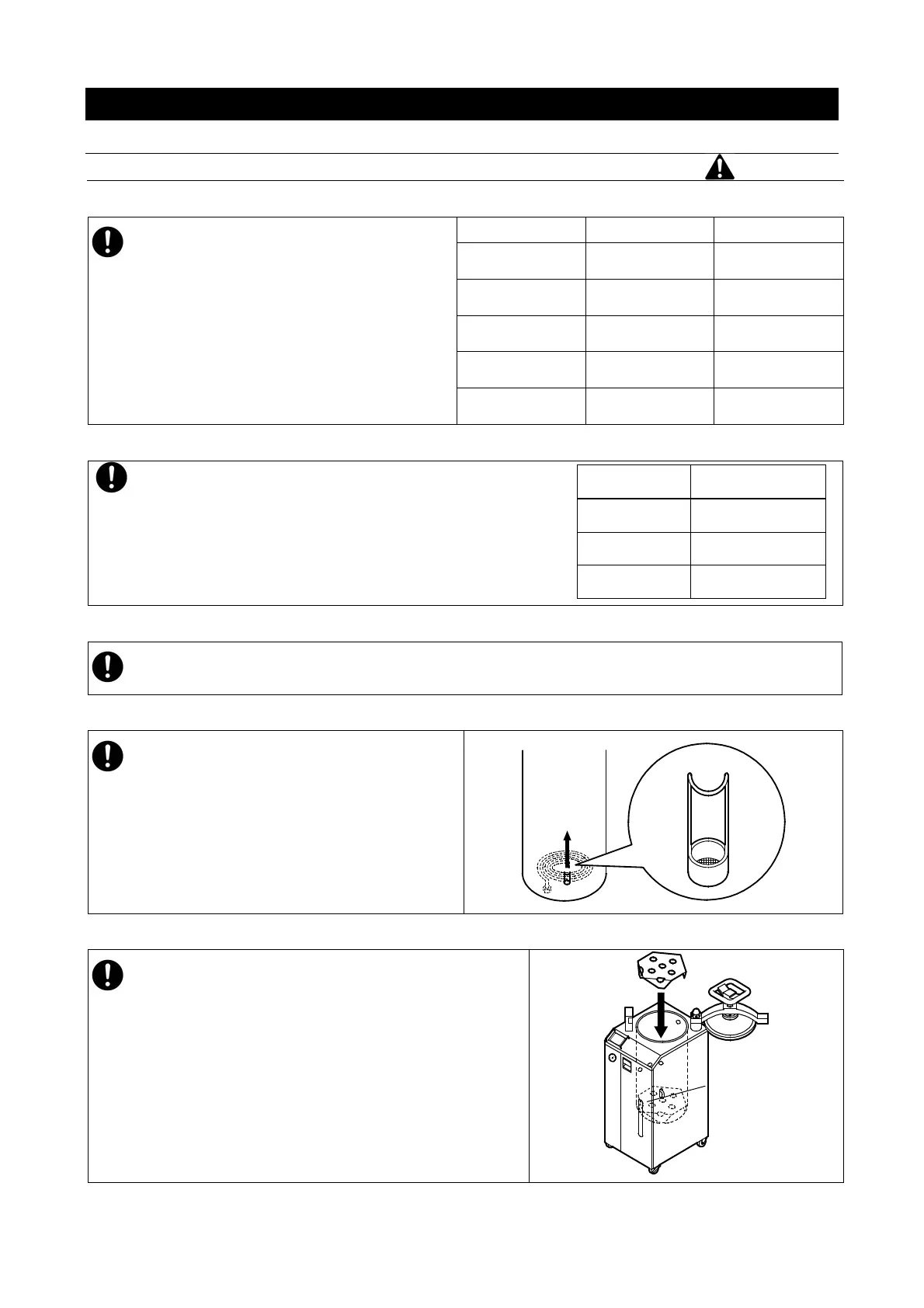
13. Install drain filter
Be sure filter is installled prior to operation.
14. Install heater baffle
The heater baffle supports process load in chamber
and protects heater 1 and sensor 2. Do not attempt to
operate unit without installing heater baffle.
Bottom Plate
(at a level)
 Loading...