39
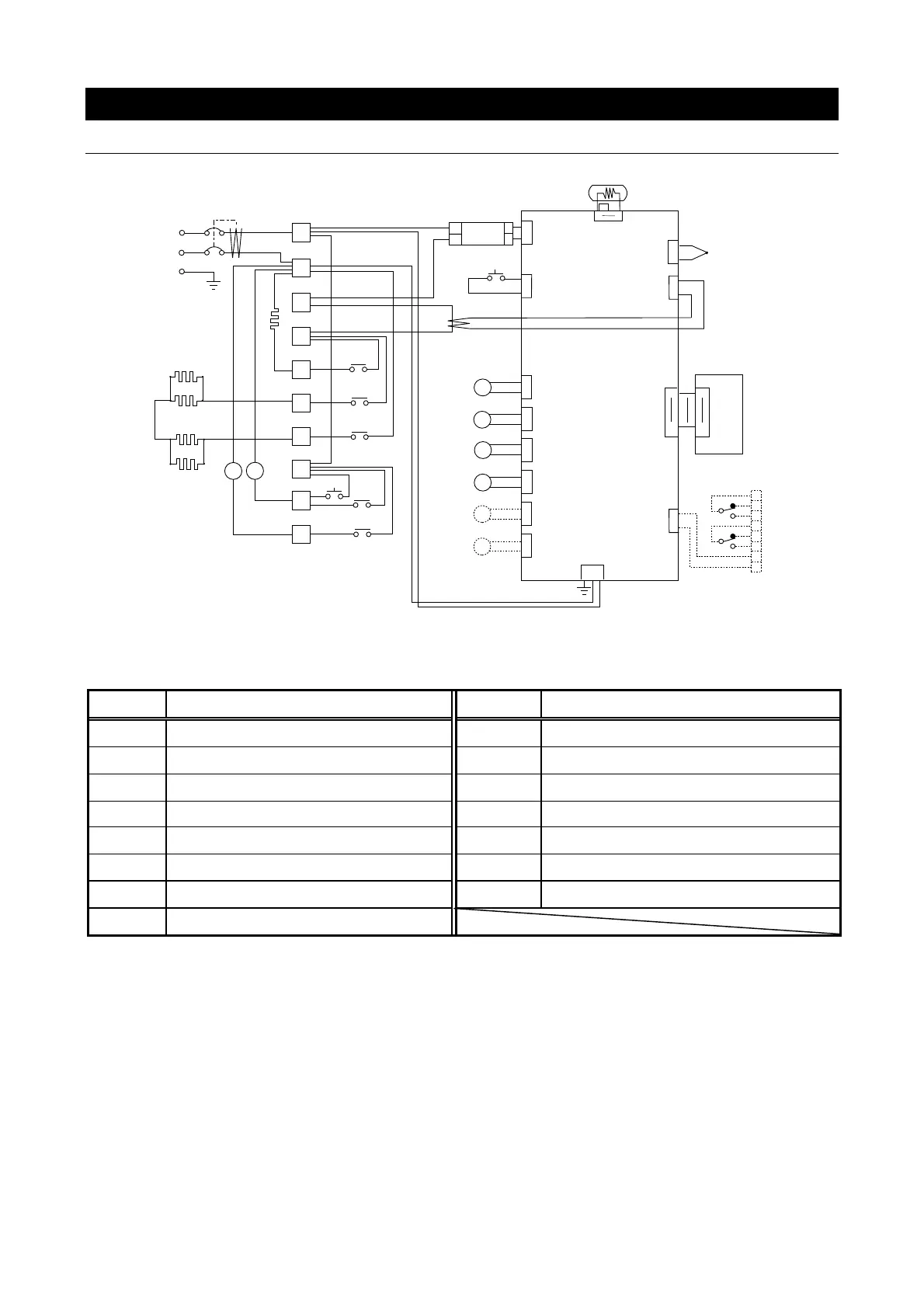
11. WIRING DIAGRAM
SM311/511
1
30
30
1
1
1
3
3
3
3
+
-
-
+
TB2
TB1
PLANAR
J1
J10
J4
J8
J9
J20
J20
PI O
TH
X3
1
3
T1
T2
CT1
H1
MCB
J1
SSR
C220V
Pt
1
2
3
4
T
5
6
7
8
9
10
MV1
X4
X1
X3
SW1
X2
3
2
J12
1
1
1
1
1
3
J15
X1
X4
MV2
X2-1
H2
H3
H4
H5
1
3
J25
SW2
13
X2-2
5 3
6 4
3
X6
3
J16
1
1
3
J17
X7
J32
1
3
1
2
3
4
5
6
8
7
TI ME-UP OUTPU
ALARM OUTPUT
TEMP. OUTPUT
+
-
X6
X7
◆ Dashed line indicates optional items
Wiring diagram glossary
Symbol
Description Symbol Description
X Relay PIO Display Board
CT Current Transformer SW1 Pressure Relief Switch
SSR Solid State Relay SW2 Micro Switch
MCB Circuit Breaker TH Sensor 2 (Thermocouple)
T Terminal Pt Sensor 1 (Pt100Ω thermometer)
MV1 Solenoid Exhaust Valve H1 Heater 1 (Sterilization)
MV2 Solenoid Drain Valve H2~5 Heater 2 (Drying)
PLANAR
Control Board