ENGINE
5-56
BY Service Manual
Camshaft and Timing Gear Train
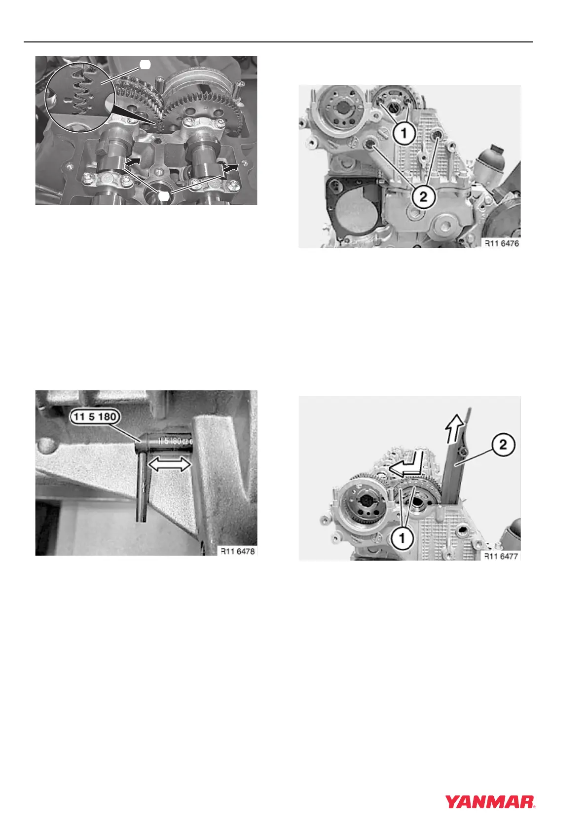
Figure 5-92
11. Rotate the crankshaft in the normal running
direction until No. 1 cylinder is at TDC of the
power stroke. The front lobe of each camshaft
(Figure 5-92, (1)) will be facing toward the
exhaust side and the timing marks
(Figure 5-92, (2)) will meet.
12. Verify position by checking the camshaft timing
marks (Figure 5-92, (2)) on gears are aligned.
The single mark on intake camshaft gear must
fall between the two marks on the exhaust
camshaft gear.
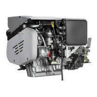
Figure 5-93
IMPORTANT
DO NOT rotate the crankshaft backward. If
the crankshaft is turned past TDC, rotate
two more turns (720°) to bring No. 1 piston
back to TDC.
13. Secure crankshaft in TDC position with flywheel
holding tool (Figure 5-93).
Figure 5-94
IMPORTANT
Do not remove the camshaft sprocket
screws without first locking the chain
tensioner in the released position.
14. Remove two remaining screws
(Figure 5-94, (1)).
15. Remove two guide rail bearing pins
(Figure 5-94, (2)).
Figure 5-95
16. Remove sprocket and chain from intake
camshaft (Figure 5-95, (1)).
17. Release guide rails (Figure 5-95, (2)) from
mount and remove.
0003771
(
2
)
(
1
)