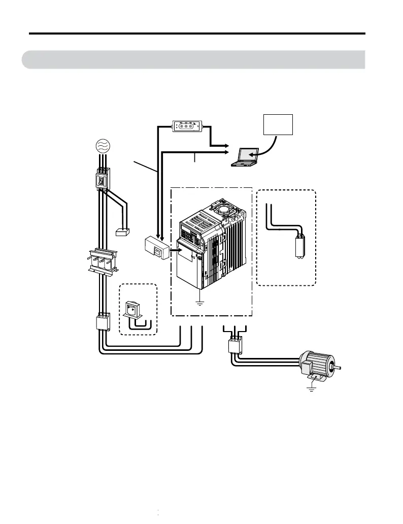
7.3 Connecting Peripheral Devices
Figure 7.1 illustrates connections between the drive, motor, and various peripheral devices.
Refer to peripheral device option manual for detailed installation instructions.
Power
supply
Line
breaker
(MCCB)
or
Leakage
breaker
AC reactor
Input side
noise filter
DC link choke
Surge
suppressor
Option
Interface
unit
U/T1 V/T2 W/T3R/L1 S/L2
+2+1
T/L3
Ground
Output side
noise filter
Ground
Motor
B1
B2
DriveWizardPlus
Drive
Braking
resistor
unit
Copy
Verify
Read
LOCK
YASKAWA
JVOP-181
USB Copy Unit
COM ERR
PC
Engineering software tools
Dedicated Cable
(RJ-45/D-sub adapter)
(30cm)
RJ-45 cable
(1m)
USB Copy Unit
(RJ-45/USB adapter)
USB cable
<1>
<2>
Figure 7.1 Connecting Peripheral Devices
<1> NOTICE: Do not connect the LAN port on a PC and the comm. port of the RS-232/C
Interface Option Unit (SI-232/J and SI-232/JC). Failure to comply may damage the option
unit and the PC. Use the USB Copy Unit with an RJ-45 cable and USB cable as shown in
Figure 7.1 to connect the drive to a PC.
7.3 Connecting Peripheral Devices
180
YASKAWA ELECTRIC TOEP C710606 26B YASKAWA AC Drive – J1000 Quick Start Guide

 Loading...


