A
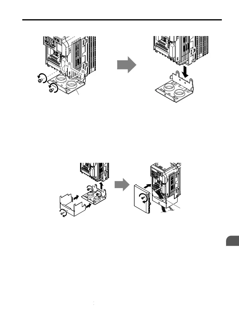
Figure 7.13 Remove the Conduit Bracket
n
Reattaching the Protective Covers
Pass power wiring and control signal wiring through the exit holes on the bottom of the conduit
bracket of the drive. Place power wiring and control signal wiring in separate conduits.
Properly connect all wiring after installing the drive and connecting other devices. Reattach
all protective covers when wiring is complete.
A
A – Pass power wiring and control signal wiring through different
exit holes at the bottom of the drive.
Figure 7.14 Reattach the Protective Covers and Conduit Bracket
7.4 Installing Peripheral Devices
YASKAWA ELECTRIC TOEP C710606 26B YASKAWA AC Drive – J1000 Quick Start Guide
195
7
Peripheral Devices &
Options

 Loading...


