Parameter Details
2
2.3 b: Application
YASKAWA TOEPYAIGA5002A GA500 DRIVE PROGRAMMING 183
Table 2.25 PID Differential Feedback Input Method
PID Differential Feedback Input Method Setting Value
MFAI terminal A1 Set H3-02 = 16 [Differential PID Feedback].
MFAI terminal A2 Set H3-10 = 16.
Note:
If you set H3-02 and H3-10 = 16, it will trigger oPE07 [Analog Input Selection Error].
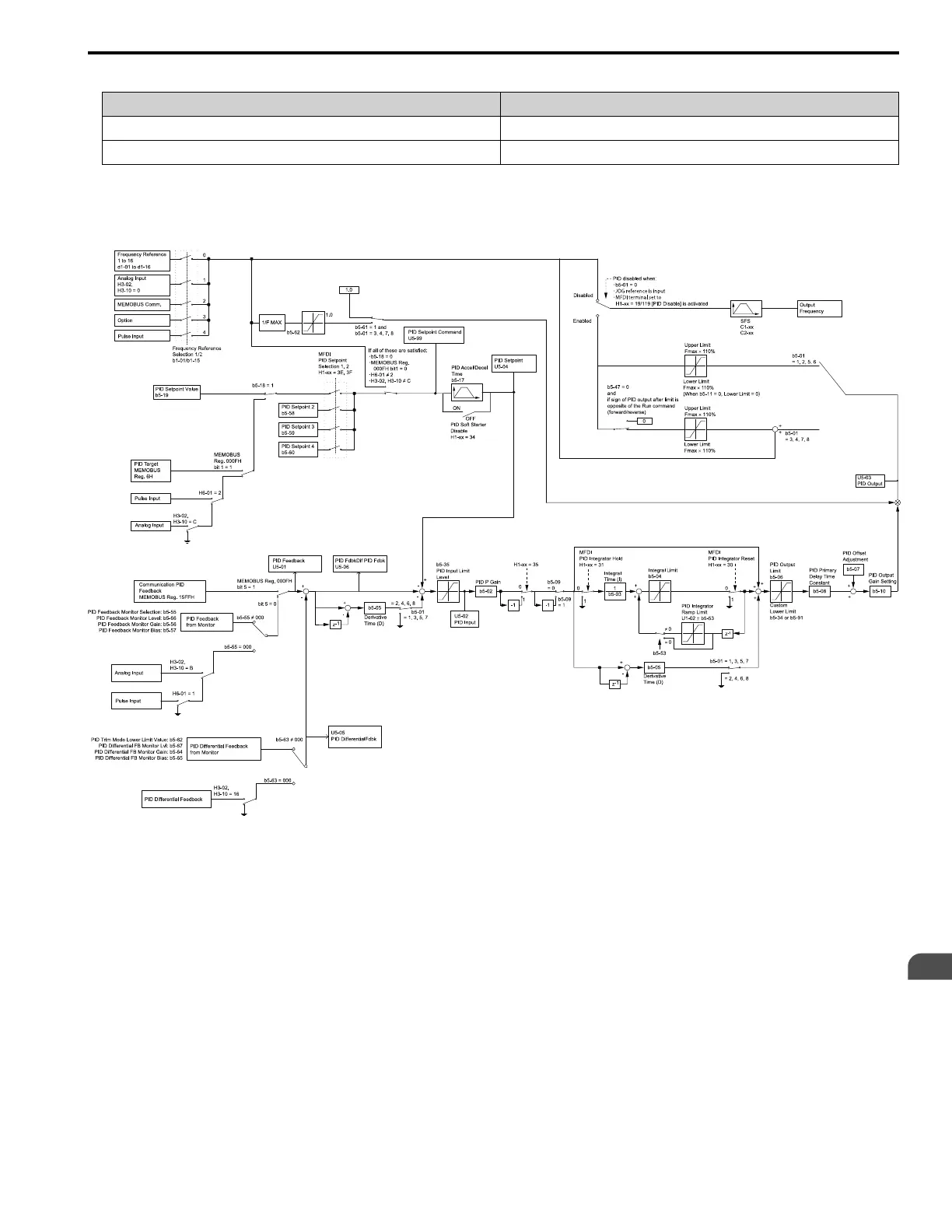
■ PID Control Block Diagram
Figure 2.22 PID Control Block Diagram
■ PID Feedback Loss Detection
The PID feedback loss detection function detects broken sensors and defective wiring between the drive and sensors.
Use the PID feedback loss detection function when you use PID control. If the feedback signal is too low, the motor
can suddenly accelerate to the maximum output frequency. This function prevents such risks to the load.
The drive uses two methods to detect feedback loss:
• PID Feedback Loss [FbL]
Set these parameters for the PID feedback loss detection function.
The drive detects feedback loss when the feedback value is less than the value in b5-13 for longer than the time in
b5-14.
– b5-12 [Feedback Loss Detection Select]
– b5-13 [PID Feedback Loss Detection Lvl]
– b5-14 [PID Feedback Loss Detection Time]

 Loading...


