Parameter Details
2
2.8 H: Terminal Function Selection
YASKAWA TOEPYAIGA5002A GA500 DRIVE PROGRAMMING 343
■ 30: DWEZ Analog Input 1
Setting Value Function Description
30 DWEZ Analog Input 1
Use with DriveWorksEZ. Refer to the DriveWorksEZ online manual for more information.
■ 31: DWEZ Analog Input 2
Setting Value Function Description
31 DWEZ Analog Input 2
Use with DriveWorksEZ. Refer to the DriveWorksEZ online manual for more information.
◆ H4: Analog Outputs
H4 parameters set the drive analog monitors. These parameters select monitor parameters, adjust gain and bias, and
select output signal levels.
■ Calibrate Meters Connected to MFAO Terminal AM
Use these parameters to calibrate meters connected to terminal AM:
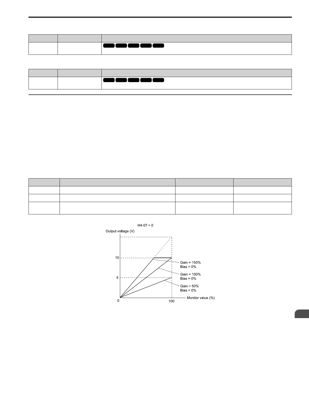
• H4-02 [Terminal AM Analog Output Gain]
• H4-03 [Terminal AM Analog Output Bias]
Set these parameters where the output voltage of 10 V and output current of 20 mA are 100% of the signal level. Use
jumper switch S5 and parameter H4-07 [Terminal AM Signal Level Select] to set the voltage output and current
output.
No. Name Range Default
H4-02 Terminal AM Analog Output Gain -999.9 - +999.9% 100.0%
H4-03 Terminal AM Analog Output Bias -999.9 - +999.9% 0.0%
H4-07 Terminal AM Signal Level Select
0: 0 +10 VDC
2: 4-20 mA
0
Figure 2.89 and Figure 2.90 show the gain and bias.
Figure 2.89 Analog Output Gain/Bias Configuration Example 1
For example, when the parameter value set to analog output is 0, and a 3 V signal is to be output to terminal AM, set
H4-03 [AM Analog Output Bias] = 30%.

 Loading...


