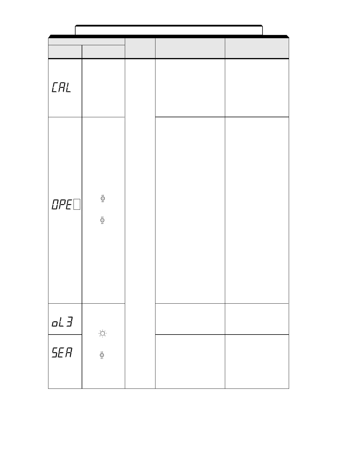
6-2
Alarm Display
Digital RUN (Green)
Drive
Explanation
Causes and
Operator ALARM (Red)
Status Corrective Actions
CAL (MODBUS Check communication
communications waiting) devices, and transmission
Correct data has not been signals.
received from the PLC
when the parameter
n003 (operation command
Blinking selection) is 2 or
n004 (frequency reference
selection) is 6,
and power is turned ON.
OPE (Parameter setting Check the setting values.
error when the parameter
setting is performed
through the MODBUS
communications)
OPE1: Two or more values
are set for multi-
function input
selection.
(parameters n050 to
n056)
OPE2: Relationship among
V / f parameters is not
correct.
(parameters n011,
n013, n014, n016)
Blinking OPE3: Setting value of
electronic thermal
standard current
exceeds 150% of
drive rated current.
Warning (parameter n036)
only. OPE4: Upper / lower limit
Fault of frequency
contacts reference is reversed.
do not (parameters n033,
change n034)
state. OPE5: (parameters n083 to
n085)
OPE9: Carrier frequency
setting is incorrect.
(parameter n080)
OL 3 (Overtorque Reduce the load, and
detection) increase the accel / decel
Motor current exceeded time.
the preset value in
Blinking parameter n098.
SEr (Sequence error) Check the external circuit
Drive receives (sequence).
LOCAL / REMOTE select
command or
Blinking communication / control
circuit terminal changing
signals from the multi-
function terminal while the
drive output is ON.
Table 6-1. Alarm Displays and Corrective Actions
- Continued
 Loading...


