A3-1
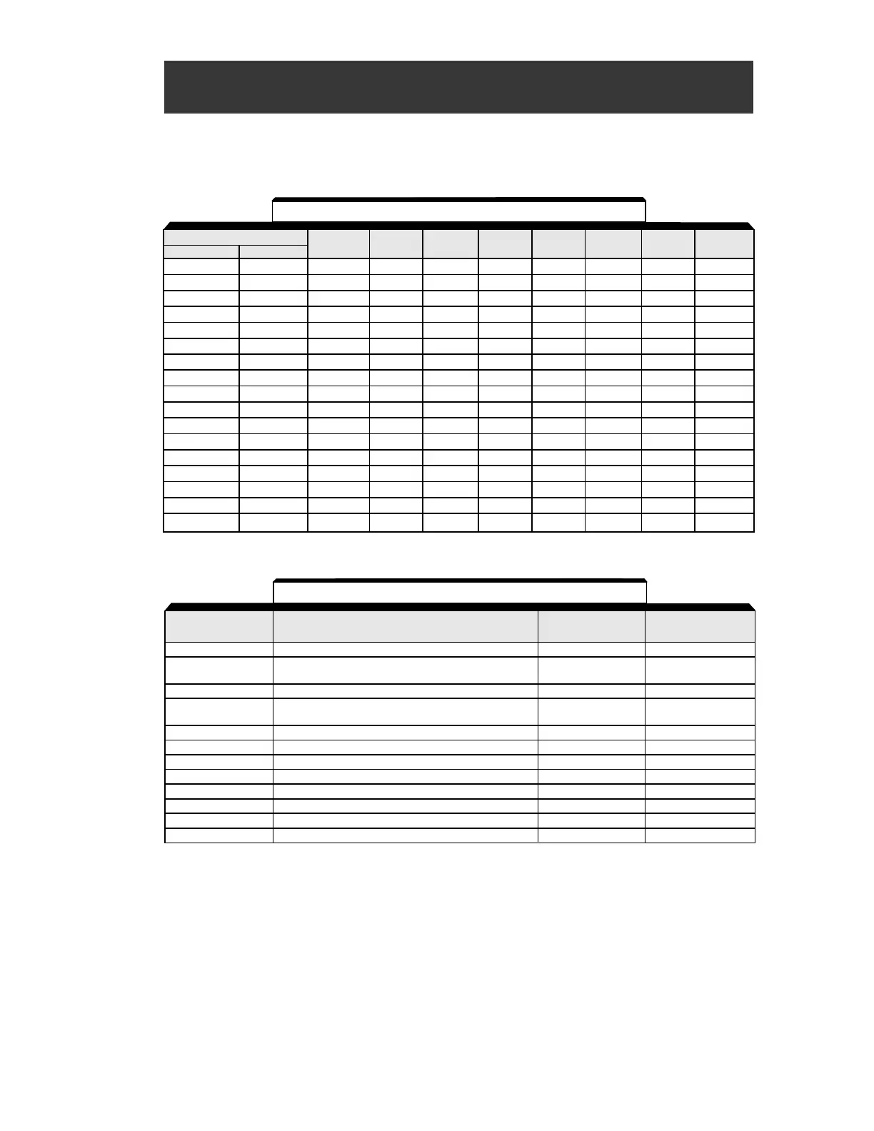
The factory setting of certain parameters change with drive rating and control method selected. The
following two tables list the parameters and how they change.
Appendix 3. CAPACITY & CONTROL METHOD
RELATED PARAMETERS
Model
CIMR-V7*U MV
n036 n105 n106 n107 n108 n110 n140 n158
20P1 A001 0.6 1.7 2.5 17.99 110.4 72 481.7 0
20P2 A002 1.1 3.4 2.6 10.28 56.08 73 356.9 1
20P4 A003 1.9 4.2 2.9 4.573 42.21 62 288.2 2
20P7 A005 3.3 6.5 2.5 2.575 19.07 55 223.7 3
21P5 A008 6.2 11.1 2.6 1.233 13.40 45 169.4 4
22P2 A011 8.5 11.8 2.9 0.800 9.81 35 156.8 5
23P7 A017 14.1 19.0 3.3 0.385 6.34 32 122.9 7
25P5 A025 19.6 28.8 1.5 0.199 4.22 26 94.8 9
27P5 A033 26.6 43.9 1.3 0.111 2.65 30 72.7 10
40P2 B001 0.6 3.4 2.5 41.97 224.3 73 713.8 21
40P4 B002 1.0 4.0 2.7 19.08 168.8 63 576.4 22
40P7 B003 1.6 6.1 2.6 11.22 80.76 52 447.4 23
41P5 B005 3.1 11.0 2.5 5.044 53.25 45 338.8 24
42P2 — 4.2 11.7 3.0 3.244 40.03 35 313.6 25
43P7 B009 7.0 19.3 3.2 1.514 24.84 33 245.8 27
45P5 B015 9.8 28.8 1.5 0.797 16.87 26 189.5 29
47P5 B018 13.3 43.9 1.3 0.443 10.59 30 145.4 30
Table A3-1. Parameters Related to Drive Capacity
V/f Control Mode Open Loop Vector
Parameter Description (n002 = 0) (n002 = 1)
n014 Frequency - Midpoint 1.5 3.0
n015 Voltage - Midpoint 12.0 (230V) 11.0 (230V)
24.0 (460V) 22.0 (460V)
n016 Frequency - Min. 1.5 1.0
n017 Voltage - Min. 12.0 (230) 4.3 (230)
24.0 (460) 8.6 (460)
n097 Overtorque Detection Selection 0.0 N/A
n104 Torque Compensation Time 0.3 0.2
n108 Motor Leakage Inductance N/A See table A3-1
n109 Torque Compensation Limit N/A 150
n111 Slip Compensation Gain 0.0 1.0
n112 Slip Compensation Time 2.0 0.2
n113 Slip Compensation Selection During Regeneration N/A 0.0
n139 Energy Saving Selection 0.0 N/A
Table A3-2. Parameters Related to Control Method
 Loading...


