5-22
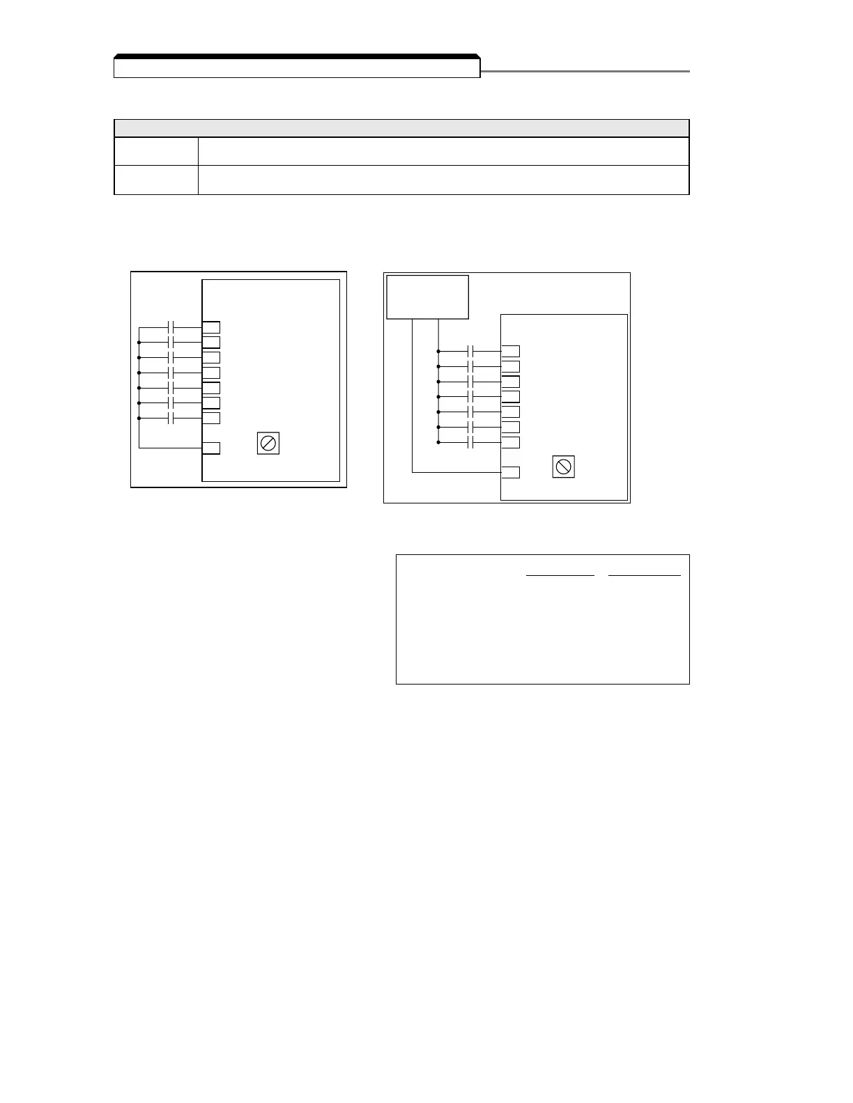
The multi-function input terminals can be activated in one of two ways:
The multi-function inputs are configured using rotary switch SW1, which is located above the upper
row of control circuit terminals and can be set with a small screwdriver.
NOTE: All power must be removed from the Drive before SW1 can be set.
(1)
Customer supplied component
n050 : Terminal S1 Function Factory settings:
2-Wire control 3-Wire control
n051 : Terminal S2 Function n050 11
n052 : Terminal S3 Function n051 22
n053 : Terminal S4 Function n052 30
n054 : Terminal S5 Function n053 55
n055 : Terminal S6 Function n054 66
n056 : Terminal S7 Function n055 77
n056 : Terminal S7 Function n056 10 10
These seven parameters select the input signal function for terminals S1 thru S7, and can be
independently set.
Parameter settings are checked whenever the enter key is pressed. A parameter set failure (Err) will
occur if any of the following conditions are detected:
• Two parameters contain the same value (n050 thru n056).
• Both the Accel/Decel Hold (data 16) and the Up/Down (data 34) functions have been selected.
Table 5-2 lists the possible data setting values and their descriptions for these parameters.
5.18 MULTI-FUNCTION INPUT TERMINALS (Term. S1-S7)
Type of input Description
NPN A contact closure must be made between a multi-function terminal (S1 to S7) and SC in order
(Factory Setting) to activate that input.
PNP
A DC voltage (+24v, 8mA max. current) must be present on a multi-function input terminal (S1 to S7)
in order to activate that input. NOTE: The minus (-) side of the 24 VDC supply must be connected to SC.
 Loading...


