4-3
4.3 STATUS INDICATOR LEDs
When using the Monitor Function, a variety of information
will appear on the Digital Operator display when each of
the U-XX (display only) parameters is selected.
CONSTANT DISPLAY
Un- MONITORED ITEM EXAMPLE
01 Frequency reference (Hz) 60.0
02 Output frequency (Hz) 60.0
03 Output current (A) 12.5
04 AC output voltage (V) 230
05 DC Bus voltage (VPN) 325
06 Input terminal status IIIIIIII
(1)
07 Output Terminal status IIIIIIII
(2)
08 Motor Torque (%) 72
(Open loop vector only)
09 Fault record (last 4 faults)
(3)
oC
10 Software number 0023
XXXX
11 Output Power (KW) 99.9
15 Data reception error IIIIIIII
(4)
16 PID Feedback (%) 35.0
17 PID Input (%) 100
18 PID Output (%) 75.5
PARAMETER DISPLAY
U - MONITORED ITEM EXAMPLE
4.4 MONITOR DISPLAYS
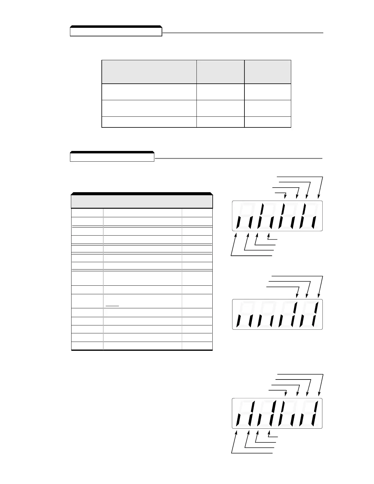
(1)
Actual display appearance:
(2)
Actual display appearance:
(3)
See section 6 for viewing
of fault log contents.
Term. S5 input OPEN
Term. S6 input CLOSED
Term. S7 input OPEN
Not used
Term. S1 input OPEN
Term. S2 input CLOSED
Term. S3 input OPEN
Term. S4 input CLOSED
(4)
Actual display appearance:
Over run error
Framing OK
Timeout error
Not used
CRC error
Data length OK
Not used
Parity error
MA-MC CLOSED
P1 - PC OPEN
P2 - PC CLOSED
Not used
{
There are two indicator LEDs on the front of the Drive. The drive status is indicated by various
combinations of ON, Blinking, and OFF conditions of these two LEDs:
For details of how the status indicator LEDs function during a drive fault, refer to the
“TROUBLESHOOTING” section.
(Green) (Red)
CONDITION RUN ALARM
Operation Ready (during stop) Blinking Off
Ramp to Stop (during decel) Long Blinking Off
Normal Operation (running) On Off
Alarm Blinking or ON Blinking
Fault Off On
 Loading...


