1-9
B. Control Circuit
All basic control circuit (signal) interconnections are shown in the appropriate diagram:
• Interconnections for external two-wire control in combination with the Digital Operator are
shown in Figure 1-5.
• Interconnections for external three-wire control in combination with the Digital Operator are
shown in Figure 1-6.
Make wire connections according to Figures 1-5 thru 1-7 and Table 1-3; observe the following:
• Signal Leads: Terminals S1-S7 & SC; RP, FS, FR & FC; R+, R-, S+, S-; & AM & AC.
• Control Leads: Terminals P1, P2 & PC; MA, MB & MC.
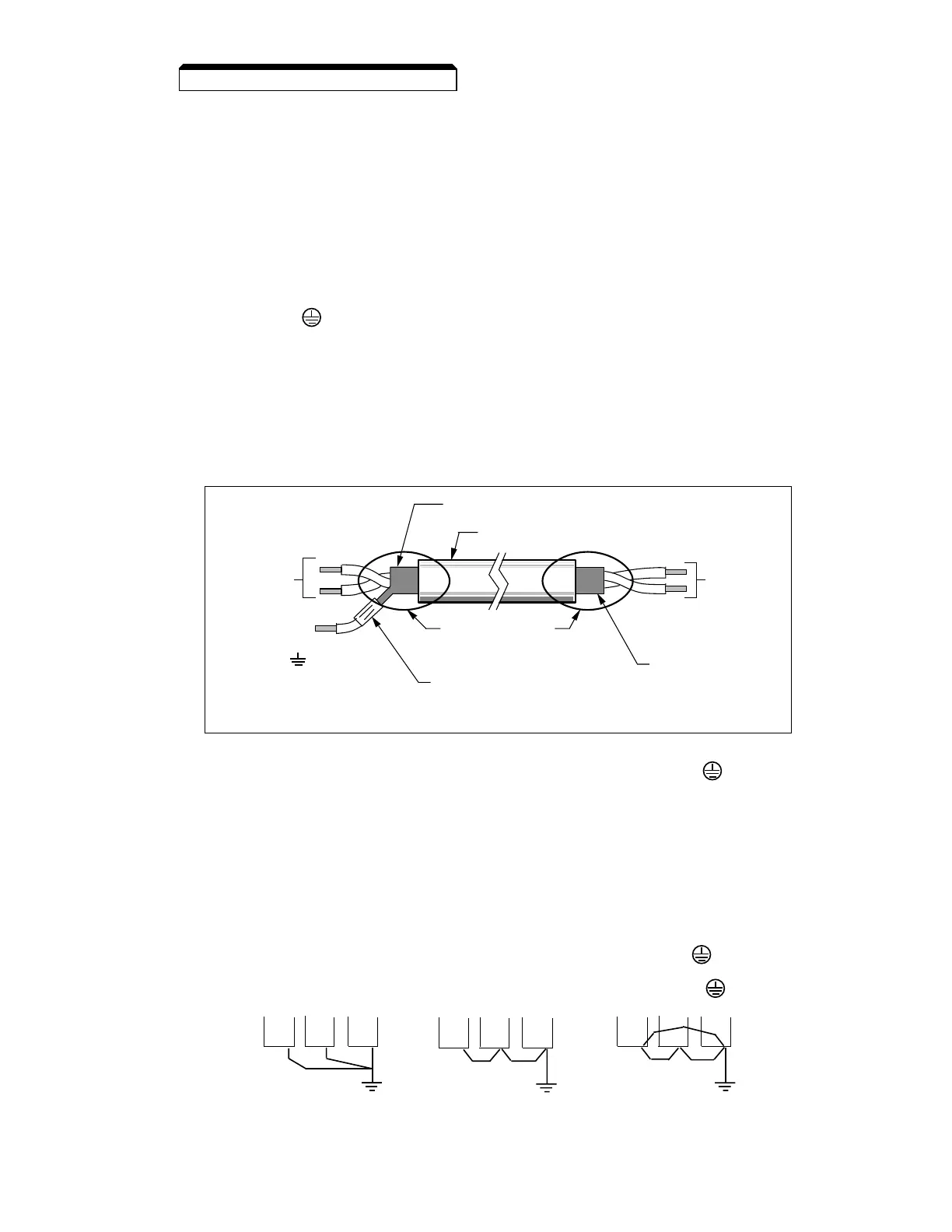
• Use twisted shielded or twisted-pair shielded wire (20-16 AWG [0.5 – 1.25mm2]) for control
and signal circuit leads. The shield sheath MUST be connected at the drive end ONLY
(terminal ). The other end should be dressed neatly and left unconnected (floating).
See Figure 1-2.
• Signal leads and feedback leads (PG) must be separated from control leads main circuit
leads, and any other power cables, to prevent erroneous operation caused by electrical
noise.
• Lead length should NOT EXCEED 164 feet (50 meters). Wire sizes should be determined
considering the voltage drop.
• All AC relays, contactors and solenoids should have RC surge supressors installed across
their coils.
• All DC relays, contactors and solenoids should have diodes installed across their coils.
Continued
1.4 ELECTRICAL INSTALLATION
•• •
•
•• •
•• •
CORRECT CORRECT NOT
ACCEPTABLE
C. Grounding
• The drive must be solidly grounded using the main circuit ground terminal .
• If Drive is installed in a cabinet with other equipment, ground leads for all equipment
should be connected to a common low-impedance ground point within the cabinet.
• The supply neutral should be connected to the ground point within the cabinet.
• Select appropriate ground wire size from Table 1-1.
• Make all ground wires as short as practical.
• NEVER ground the drive in common with welding machines, or other high power electrical
equipment.
• Where several drives are used, ground each directly to the ground point (see Figure 1-1).
DO NOT FORM A LOOP WITH THE GROUND LEADS.
• When connecting a motor to the drive’s output terminals, include a separate ground wire.
Attach ground wire solidly to motor frame and to drive’s ground terminal .
• When using armored or shielded cable for connection between drive and motor, solidly
connect armor or shield to motor frame, and to the drive’s ground terminal .
 Loading...


