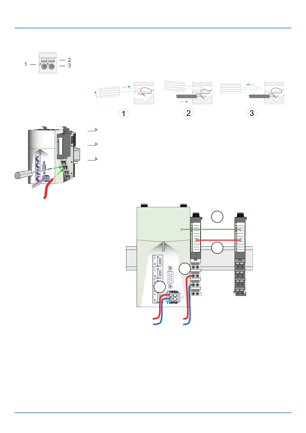
1 Pin no. at the connector
2 Opening for screwdriver
3 Connection hole for wire
1. Insert a suited screwdriver at an angel into the square opening as shown. Press
and hold the screwdriver in the opposite direction to open the contact spring.
2. Insert the stripped end of wire into the round opening. You can use wires with a
cross section of 0.08mm
2
up to 1.5mm
2
.
3. By removing the screwdriver, the wire is securely fixed via the spring contact to the
terminal.
0V
DC24V
0V
DC24V
DC 24V
SysDC5V
...
1
2
3
4
(1) DC 24V supply CPU:
DC 5V electronic section supply I/O area (max. 2A)
(2) Power module 007-1AB00:
DC 24V power section supply (max. 10A)
(3) DC 5V electronic section supply I/O area
(4) DC 24V power section supply I/O area
Wiring proceeding
Standard wiring
iC9200 Series
Basics and mounting
Wiring > Wiring System SLIO periphery
HB700 | CPU | PMC921xEx | en | 23-06 22

 Loading...


