You have the option to remove the connector of the power supply, e.g. for a module
change with fixed wiring. For this the connector has a locking lever. The connector is
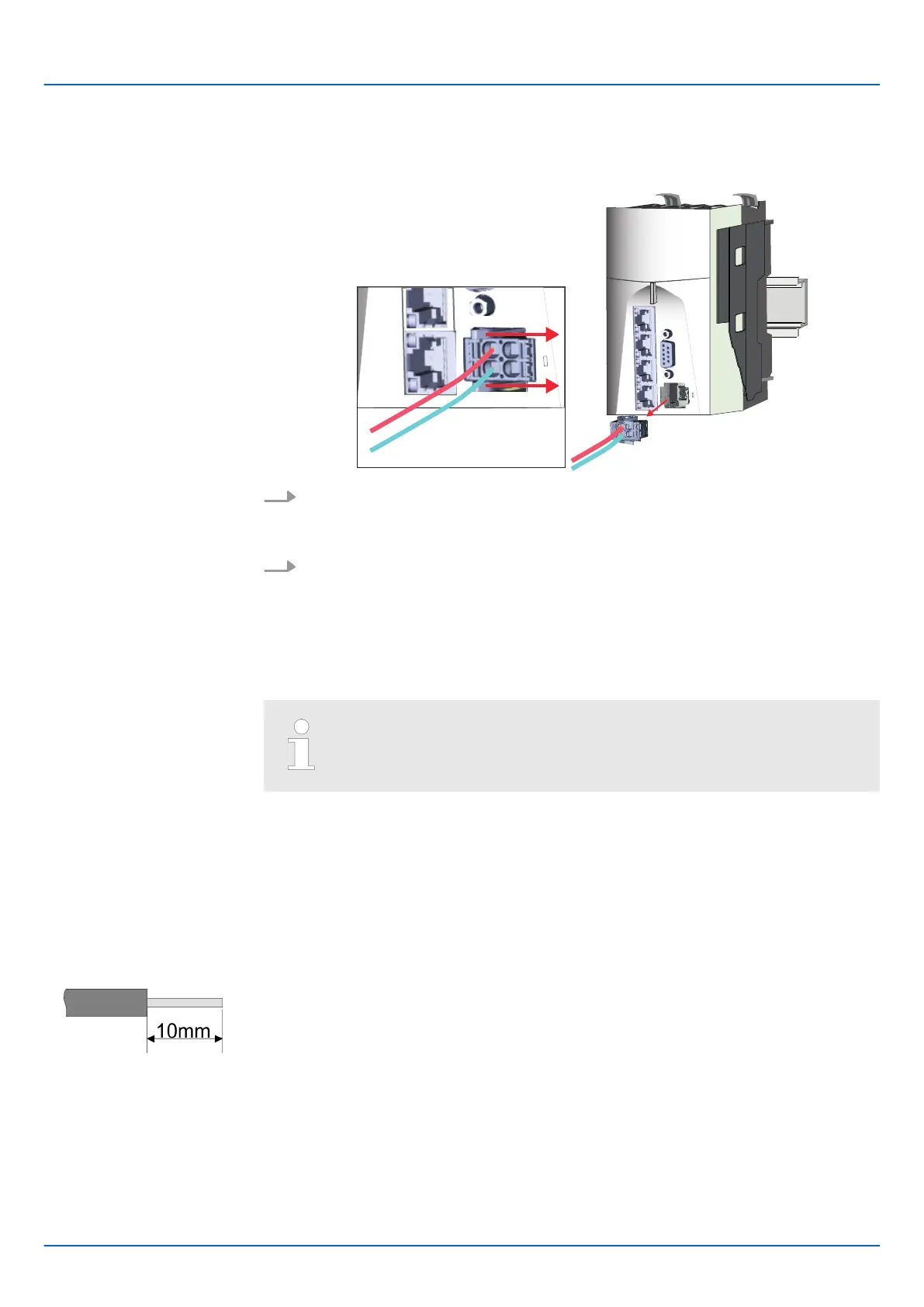
removed as follows:
1. Remove connector:
By pressing the release button as shown, the connector is released and can be
removed.
2. Plug connector:
The connector is plugged by plugging it directly into the release lever. Here, the
locking levers return to their original position.
2.5.2 Wiring System SLIO periphery
When using System SLIO modules, you must always mount the power
module 007-1AB00 - DC 24V 10A, because the CPU does not provide a
power section supply due to the system.
2.5.2.1 Wiring power module
With the power module, terminals with spring clamp technology are used for wiring. The
spring clamp technology allows quick and easy connection of your supply lines. In con-
trast to screw terminal connections this type of connection is vibration proof.
U
max
30V DC
I
max
10A
Cross section
0.08 ... 1.5mm
2
(AWG 28 ... 16)
Stripping length 10mm
Remove connector
Terminal module terminals
Data
iC9200 Series
Basics and mounting
Wiring > Wiring System SLIO periphery
HB700 | CPU | PMC921xEx | en | 23-06 21

 Loading...


