3.2 Structure
3.2.1 CPU iC921xM-x
1
3
4
5
6
7
8
9
10
11
1
14
13
12
15
17
16
2
3
4
5
6
7
8
9
10
11
18
19
PW: ... SN: ...PMC921...
MAC1: ...
MAC2: ...
1
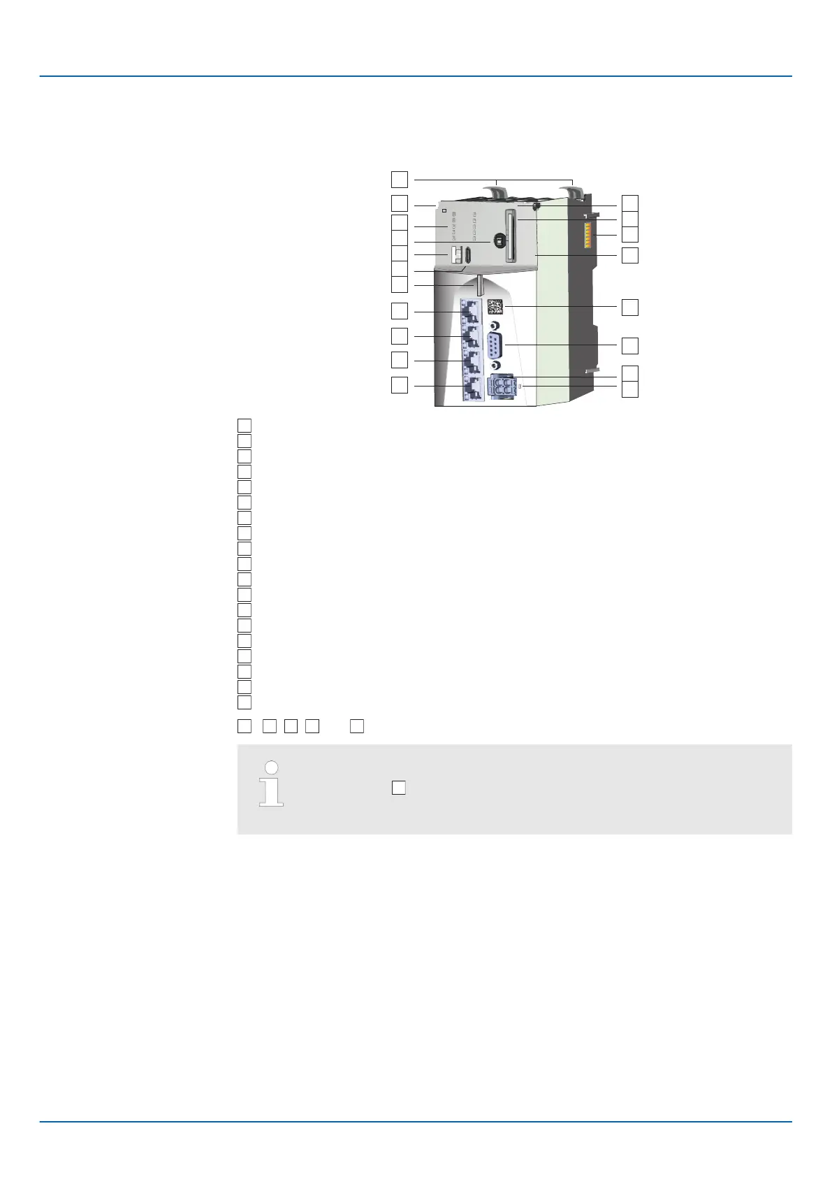
Locking lever
Order number and hardware revision version [1]
LED bars
Operating mode switch CPU
S1: DIP switch
X7: USB-C jack
Status LED
X1: EtherCAT port
X2: Optional
X3: Ethernet port (internally switched with X4)
X4: Ethernet port (internally switched with X3)
Password and serial number
Slot for Yaskawa SD card
SliceBus for System SLIO modules
MAC1: MAC address for X3/X4, MAC2: MAC address for X1/X2
QR code
X5: reserved
X6: Connector DC 24V power supply
LED DC 24V power supply
...
,
,
and
are located under the front flap.
Direct access to product information
The QR code
at the front takes you to the product-specific website.
You will find there all information for deployment and operation of the
CPU.
iC9200 Series
Hardware description
Structure > CPU iC921xM-x
HB700 | CPU | PMC921xEx | en | 23-06 44

 Loading...


