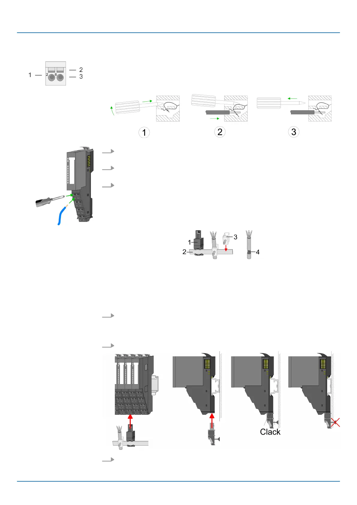
1 Pin no. at the connector
2 Opening for screwdriver
3 Connection hole for wire
1. Insert a suited screwdriver at an angel into the square opening as shown. Press
and hold the screwdriver in the opposite direction to open the contact spring.
2. Insert the stripped end of wire into the round opening. You can use wires with a
cross section of 0.08mm
2
up to 1.5mm
2
.
3. By removing the screwdriver, the wire is securely fixed via the spring contact to the
terminal.
1 Shield bus carrier
2 Shield bus (10mm x 3mm)
3 Shield clamp
4 Cable shield
To attach the shield the mounting of shield bus carriers are necessary. The shield bus
carrier (available as accessory) serves to carry the shield bus to connect cable shields.
1. Each 8x periphery module has a carrier hole for the shield bus carrier. Push the
shield bus carrier, until they engage into the module. With a flat mounting rail for
adaptation to a flat mounting rail you may remove the spacer of the shield bus car-
rier.
2. Put your shield bus into the shield bus carrier.
3. Attach the cables with the accordingly stripped cable screen and fix it by the shield
clamp with the shield bus.
Wiring proceeding
Shield attachment
iC9200 Series
Basics and mounting
Wiring > Wiring System SLIO periphery
HB700 | CPU | PMC921xEx | en | 23-06 24

 Loading...


