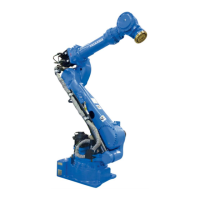
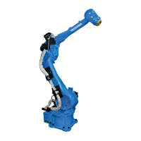
Internal cables and compressed air lines
8 - 47
Fig. 8-2: Details of the plug
The pins used on the connectors (3BC: 4 wires 1.25 mm², 2 wires x 0.75 mm² and 8 wires
x 0.2 mm²) are connected to the stand and arm with individual wires.
The internal connections of the robot are shown in the following diagrams "Connection
diagram A" and "Connection diagram B".
= assigned
= unassigned
Detailed drawing (base) Detailed drawing (casing)
Pins used +24 V (1A) for shock sensor
7 and 8 are open Shock sensor signal input
12
13(1.25mm
2
)
11
14(1.25mm
2
)
15(1.25mm
2
)
16(1.25mm
2
)
14
15
13
16
10
12(0.75mm
2
)
11(0.75mm
2
)
5
9
6
1
3
4
2
6
4
9
1
7
2
5
8
3
10
12
13(1.25mm
2
)
11
14(1.25mm
2
)
15(1.25mm
2
)
16(1.25mm
2
)
14
15
13
16
10
12(0.75mm
2ࠉ
)
5
9
6
1
3
4
2
6
4
9
1
7
2
5
8
3
10
8
7
8
7
11(0.75mm
2
)
1
2
2
5
6
3
4
1
4
2
5
3
6