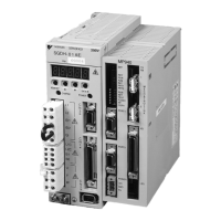
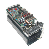
MotionSuite™ MP940 Machine Controller Hardware Manual Section 13: Dimensional Drawings and Cable Diagrams
65
I/O Connector
Number Signal Name Reference Number Signal Name Reference
1 AO Analog Input 26 AO_GND Analog Output Ground
2— — 27— —
3— — 28— —
4 PA+ A_ Pulse + 29 PB+ B_Pulse +
5 PA- A_ Pulse - 30 PB- B_Pulse -
6 GND Pulse Input
Ground
31 GND Pulse Input Ground
7— — 32— —
8— — 33— —
9 PILC 5V PI Latch Input
Common (5V)
34 PILC 12V PI Latch Input
Common (12V)
10 PILC 24V PI Latch Input
Common (24V)
35 PIL PI Latch Input Common
12 — — 36 — —
12 — — 37 — —
13 DC 24V DI Power (input) 38 DC 24V DI Power (input)
14 DI_00 DI_00
Input
(DI interrupt)
39 DI_01 DI_01 Input
15 DI_02 DI_02 Input 40 DI_03 DI_03 Input
16 DI_04 DI_04 Input 41 DI_05 DI_05 Input
17 DI_06 DI_06 Input 42 DI_07 DI_07 Input
18 — — 43 — —
19 — — 44 — —
20 DC 24V DO Power (input) 45 DC 24V DO Power (input)
21 DO_00 DO_00 Output 46 DO_01 DO_01 Output
22 DO_02 DO_02 Output 47 DO_03 DO_03 Output
23 DO_04 DO_04 Output 48 DO_05 DO_05 Output
24 DO_06 DO_06 Output 49 DO_07 DO_07
Output (Counter
coincidence output)
25 DO_GND DO Ground(0V) 50 DO_GND DO Ground(0V)
Figure 13.6: I/O Connector
Artisan Technology Group - Quality Instrumentation ... Guaranteed | (888) 88-SOURCE | www.artisantg.com

 Loading...


