7.1.3 Connector CN2A
No Signal Pin Function Dir. No Signal Pin Function Dir.
1
N.C.
*2
OUT 14 -
N.C.
*2
I/O
2
N.C.
*2
OUT 15 -
N.C.
*2
I/O
3 V Hall Signal V +
*1
IN 16 W Hall Signal W +
*1
IN
4 U Hall Signal U +
*1
IN 17 PG_0V Ground -
5 /C(Z) Pulse /C(Z) - 18 -
N.C.
*2
-
6 C(Z) Pulse C(Z) - 19 -
N.C.
*2
-
7 -
N.C.
*2
- 20 -
N.C.
*2
-
8 PG+5 V
Power
*3
OUT 21 -
N.C.
*2
-
9 PG+5 V
Power
*3
OUT 22 -
N.C.
*2
-
10 PG+5 V
Power
*3
OUT 23 A Pulse A -
11 PG_0V Ground - 24 /A Pulse /A -
12 PG_0V Ground - 25 B Pulse B -
13 PG_0V Ground - 26 /B Pulse /B -
*1 Without hall sensor, do not connect to any signals. With hall sensor, please refer to
Ä
Chap. 8 ‘Hall Sensor Signals Interface’ page 46, too.
*2 Pins denoted as N.C. do not connect to any signals.
*3 If higher voltage is necessary, e. g. for compensation of long cables, contact
YASKAWA support.
6
5
4
1
14 26
3 13
2
15
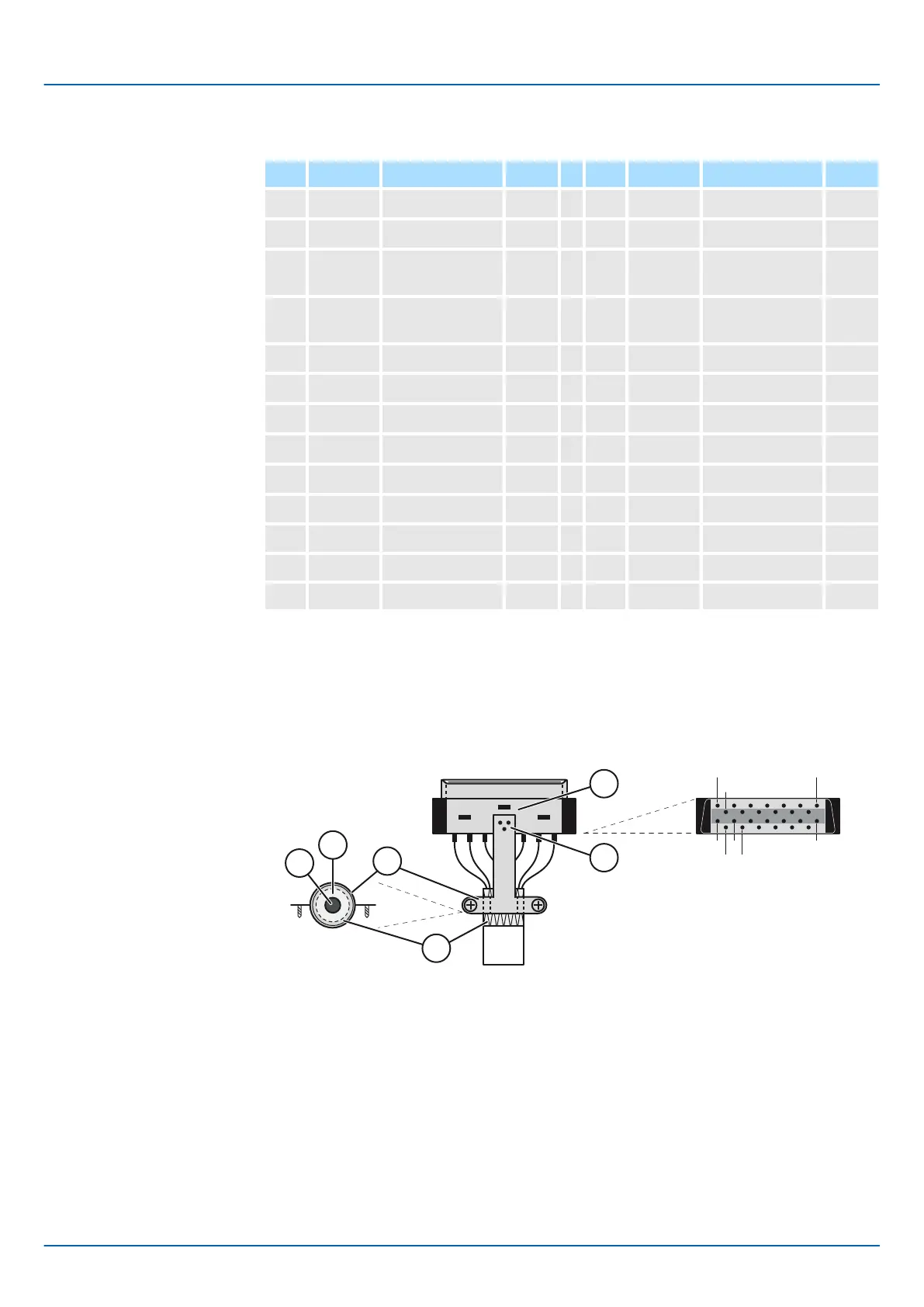
4
Pin
View from solder side
2
1
3
1. To achieve proper strain relief, increase cable (4) diameter with copper tape (5), if
necessary. Connect the cable to the cable clamp (6).
2. Strip back cable shielding (1) over tape winding to achieve a large surface area con-
nection between cable shield and clamp across complete cable circumference. The
metal plate (2) must be soldered to the plug (3).
3. Use signal cables with twisted pairs and at least over all shielding only!
Sigma-5 and Sigma-7 Series SERVOPACKs
Encoder Interfaces
A quad B Pulse interface > Connector CN2A
| | Feedback Option Module Type 3 - Manual version C - Revision 0 | en | 45

 Loading...


