7 Encoder Interfaces
This chapter describes the encoder interfaces of the Feedback Option Module.
7.1 A quad B Pulse interface
7.1.1 Overview
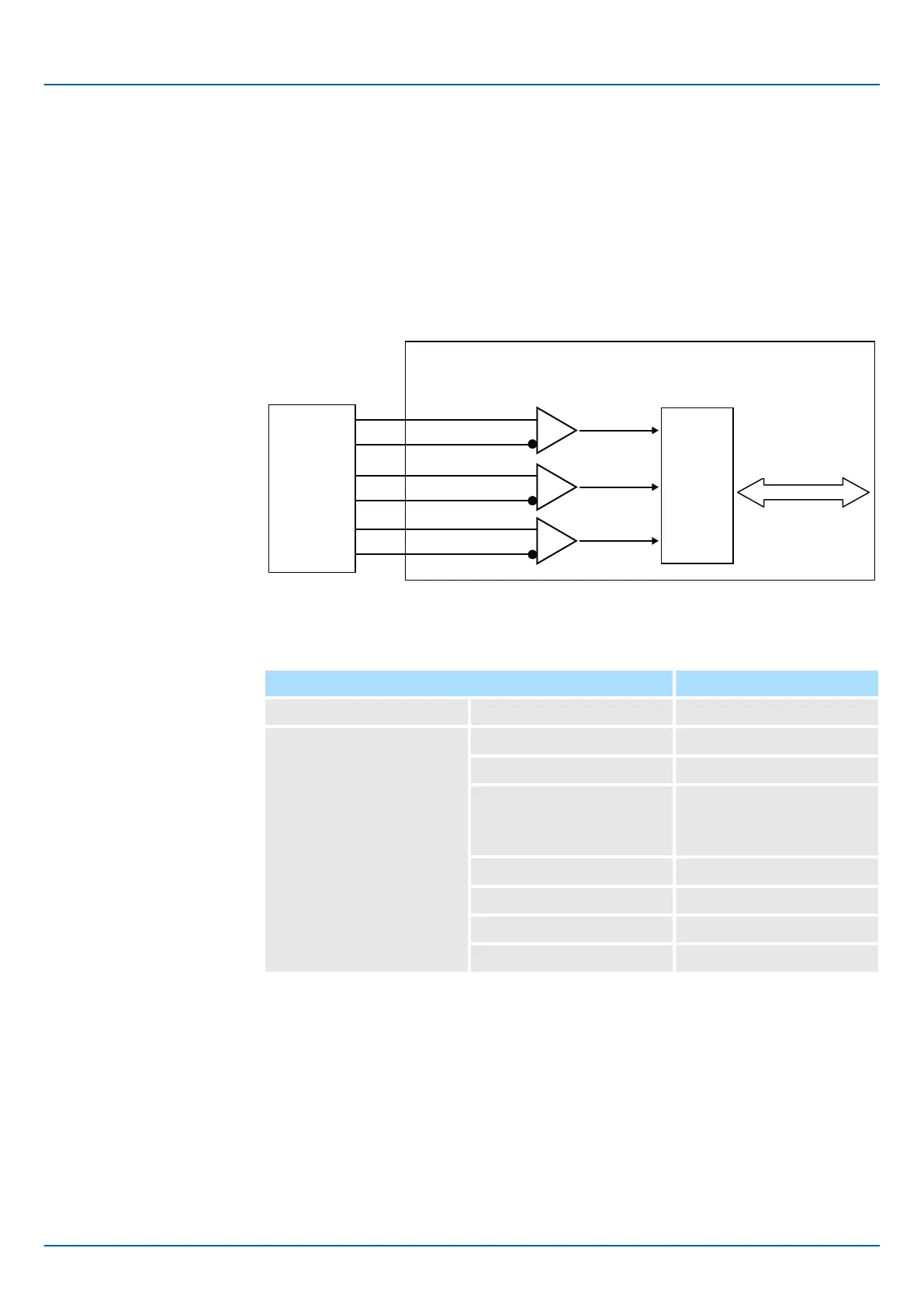
A quad B pulse signal is counted on each edge in the master. The block diagram of the
interface is shown below.
A quad B
Pulse
encoder
Encoder Master
A
B
FPGA
REF
Servo
Serial
I/F
7.1.2 Technical Data
Items Description
Encoder Supply Output voltage Typically 5 V
Incremental Encoder Input Signal form Square wave pulse
Evaluation 4x
Max. input frequency 1 MHz
4 MHz
(SGDV-OFB03A-G2 only)
Max. counter frequency 4 MHz
Max. reference frequency 1 MHz
Distance between edges 0.2 μsec or more
Differential voltage 0.2 V or more
Sigma-5 and Sigma-7 Series SERVOPACKs
Encoder Interfaces
A quad B Pulse interface > Technical Data
| | Feedback Option Module Type 3 - Manual version C - Revision 0 | en | 44

 Loading...


