INSPECTION AND MAINTENANCE
5.2.3 Servopack Connection Diagrams
— 5-18 —
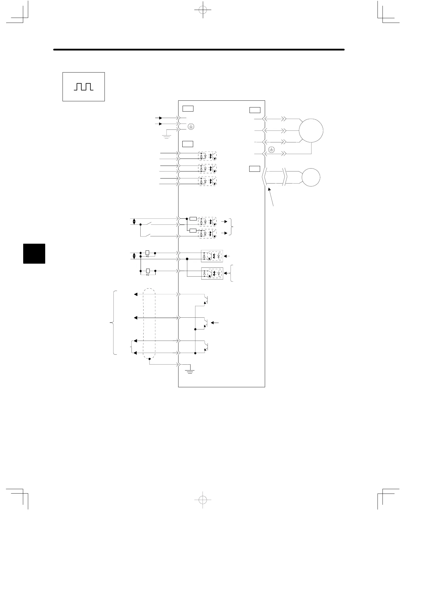
Instrument Connection Examples (for Position Control)
CN3
CN1
2
24VDC
GND
3
8
7
3
PBO
PAO
PCO
FG
1
+24V
+24VIN
IN1
9
1
2IN2
1Ry
2Ry
ALM
SG-COM
3Ry
4Ry
OUT2
11
12
10
13
20
15
14
17
16
19
18
PULS
/PULS
SIGN
/SIGN
CLR
/CLR
+24V
Input Power Supply
24 VDC ±10%
Reference Pulses
(450 kpps Max.)
Error Counter Clear
Signal (Active, High)
/S-ON
/P-COM
/ALMRST
/CL
(set in parameters)
5Ry OFF for Servo
Alarm
Servopack
(SGDF-jjCP)
PG Output
Open Collector
Note 1: The capacity of each output circuit is below 30 VDC and 50 mA.
2: Signal input line ↕P represents twisted-pair cable.
3: I/O power supply (+24 V) must be prepared by customers.
Correctly terminate
end of shielded cable.
Servo Alarm
Open Collector
/S-ON
/P-COM
/ALMRST
/CL
ALM, /TGON, /BK,
/COIN, /CLT
(set in parameters)
ALM, /TGON,
/BK, /COIN,
/CLT
Phase
A
Phase
B
Phase
C
0V
Servomotor
0V
M
U
V
W
CN4
CN2
1
3
4
2
PG
5
Positions
Artisan Technology Group - Quality Instrumentation ... Guaranteed | (888) 88-SOURCE | www.artisantg.com

 Loading...


