6 Control Circuit Wiring
YASKAWA America, Inc. PL.GA500.01 YASKAWA AC Drive - V1000 to GA500 Transition Guide 23
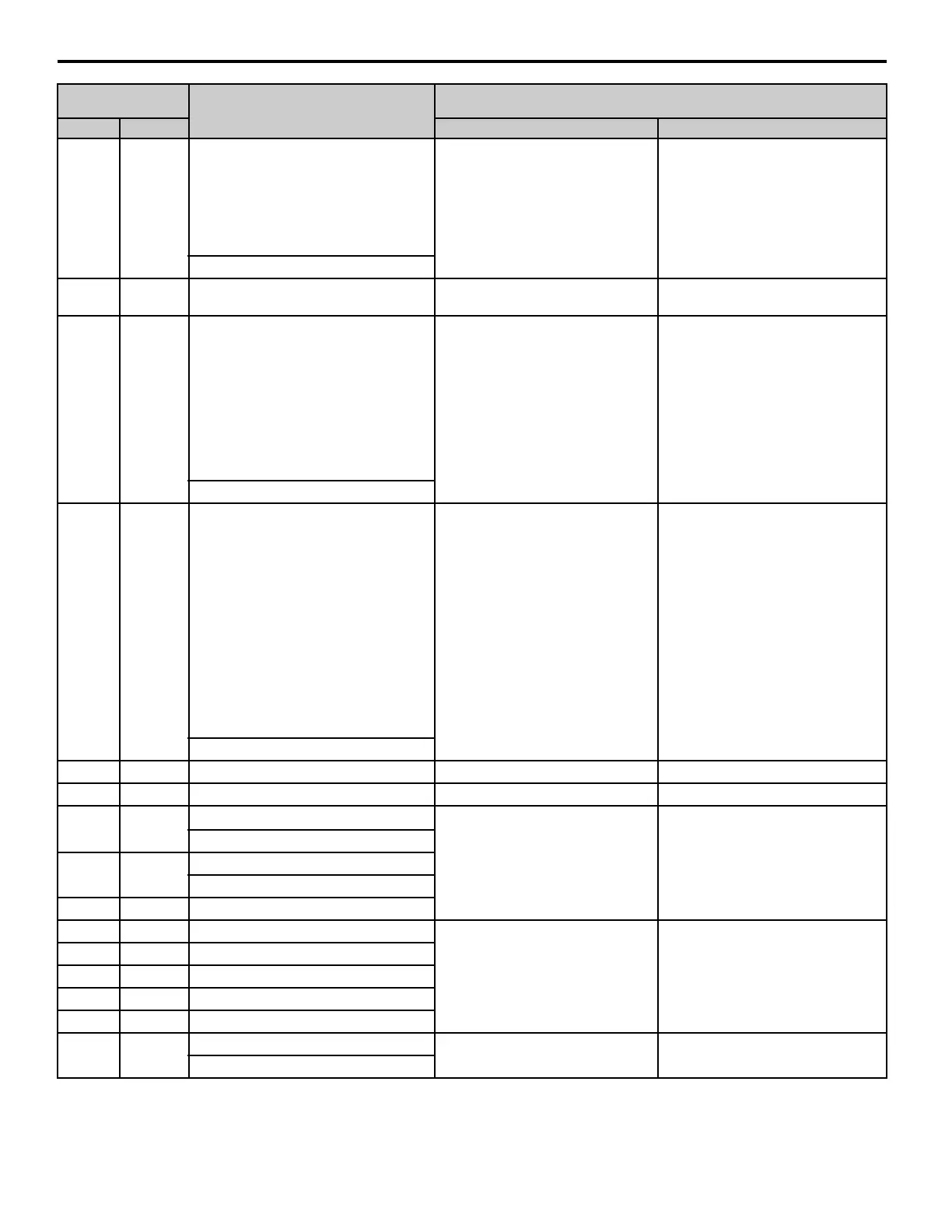
RP RP
Master frequency reference pulse train
input
Response frequency: 0.5 to 32 kHz
(Duty Cycle: 30 to 70%)
(High level voltage: 3.5 to 13.2 Vdc)
(Low level voltage: 0.0 to 0.8 Vdc)
(Input impedance: 3 kΩ)
Response frequency: 0.5 to 32 kHz
(Duty Cycle: 30 to 70%)
(High level voltage: 3.5 to 13.2 Vdc)
(Low level voltage: 0.0 to 0.8 Vdc)
(Input impedance: 3 kΩ)
(Master frequency reference)
+V +V Power supply for frequency setting
+10.5 Vdc
(Allowable current 20 mA maximum)
+10.5 Vdc
(Allowable current 20 mA maximum)
A1 A1
Multi-function analog input 1
Input voltage 0 to +10 Vdc
(20 kΩ) resolution 1/1000
Voltage input
Use H3-01 [Terminal A1 Signal Level
Select] to select the signal level.
• 0 V to 10 V/100%
(input impedance: minimum 15 kΩ)
• -10 V to +10 V/-100% to +100%
(Input impedance: minimum 15 kΩ)
Master frequency reference
A2 A2
Multi-function analog input 2
Input voltage or input current
(Selected by DIP switch S1 and
H3-09)
0 to +10 Vdc (20 kΩ),
Resolution: 1/1000
4 to 20 mA (250 Ω) or
0 to 20 mA (250 Ω)
Resolution: 1/500
Voltage input or current input
Use DIP switch S1 and H3-09
[Terminal A2 Signal Level Select] to
select the input.
0 V to 10 V/100%
(Input impedance: minimum 15 kΩ)
-10 V to +10 V/-100% to +100%
(Input impedance: Minimum 15 kΩ)
4 mA to 20 mA/100%,
0 mA to 20 mA/100%
(Input impedance: 250 Ω)
(Combined to terminal A1)
AC AC Frequency reference common 0 V 0 V
E (G) E (G) Connecting shielded cable - -
MA MA
N.O. output
Relay output
30 Vdc, 10 mA to 1 A
250 Vac, 10 mA to 1 A
Minimum load: 5 Vdc, 10 mA
(Reference value)
Relay output
30 Vdc, 10 mA to 1 A
250 Vac, 10 mA to 1 A
Minimum load: 5 Vdc, 10 mA
(Reference value)
(Fault)
MB MB
N.C. output
(Fault)
MC MC Digital output common
P1 P1 Multi-function photocoupler output 1
Photocoupler output 48 Vdc,
2 to 50 mA
Photocoupler output 48 V,
2 to 50 mA
- C1 (During RUN)
P2 P2 Multi-function photocoupler output 2
- C2 (Speed agree 1)
PC - Photocoupler common
MP MP
Pulse train output
32 kHz (Maximum) 32 kHz (Maximum)
(Output frequency)
Control Circuit
Terminals
Name
Signal Level
V1000 GA500 V1000 GA500

 Loading...


