6 Control Circuit Wiring
24 YASKAWA America, Inc. PL.GA500.01 YASKAWA AC Drive - V1000 to GA500 Transition Guide
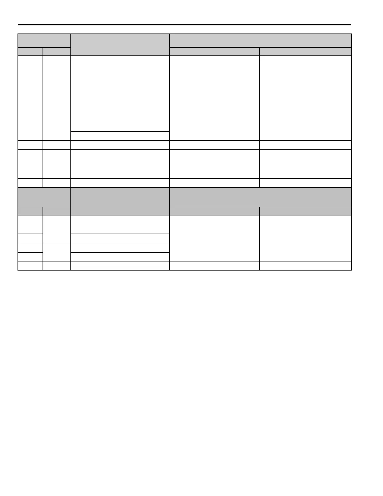
AM AM
Analog monitor output
0 to 10 Vdc (2 mA or less)
Resolution: 1/1000
Select voltage or current output.
0 V to 10 V/0% to 100%
4 mA to 20 mA (Receiver
recommended impedance: 250 Ω)
Note:
Use jumper S5 and H4-07 [Terminal
AM Signal Level Select] to set the
signal type.
(Output frequency)
AC AC Monitor common 0 V 0 V
- PS External 24 V power supply input -
Supplies backup power to the drive
control circuit, keypad, and option
board.
21.6 Vdc to 26.4 Vdc, 700 mA
- AC External 24 V power supply ground - 0 V
Serial
Communication
Terminal
Name
Signal Level
V1000 GA500 V1000 GA500
R+
D+
Communications input (+)
RS-485/422 MEMOBUS/ Modbus
communication protocol 115.2 kbps
(Maximum)
RS-485 MEMOBUS/ Modbus
communication protocol 115.2 kbps
(Maximum)
R- Communications input (-)
S+
D-
Communications output (+)
S- Communications output (-)
IG AC Shield ground 0 V 0 V
Control Circuit
Terminals
Name
Signal Level
V1000 GA500 V1000 GA500

 Loading...


