1-9
B. Control Circuit
All basic control circuit (signal) interconnections are shown in the appropriate diagram:
• Interconnections for external two-wire control in combination with the Digital Operator are shown in
Figure 1-5.
• Interconnections for external three-wire control in combination with the Digital Operator are shown in
Figure 1-6.
Make wire connections according to Figures 1-5 thru 1-7 and Table 1-3; observe the following:
• Signal Leads: Terminals S1-S7 & SC; RP, FS, FR & FC; R+, R-, S+, S-; & AM & AC.
• Control Leads: Terminals P1, P2 & PC; MA, MB & MC.
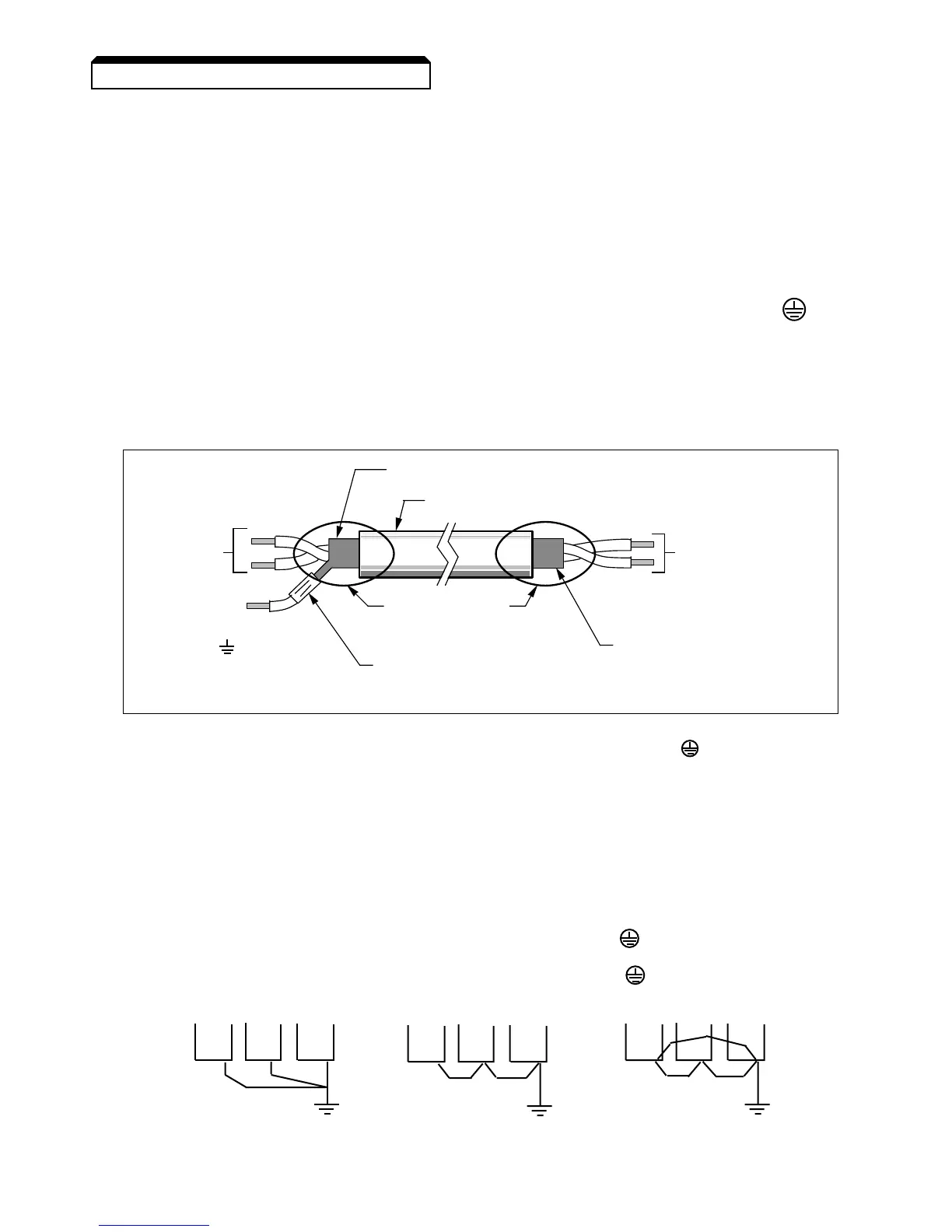
• Use twisted shielded or twisted-pair shielded wire (20-16 AWG [0.5 – 1.25mm2]) for control and sig-
nal circuit leads. The shield sheath MUST be connected at the drive end ONLY (terminal ). The
other end should be dressed neatly and left unconnected (floating). See Figure 1-2.
• Signal leads and feedback leads (PG) must be separated from control leads main circuit leads, and
any other power cables, to prevent erroneous operation caused by electrical noise.
• Lead length should NOT EXCEED 164 feet (50 meters). Wire sizes should be determined consider-
ing the voltage drop.
• All AC relays, contactors and solenoids should have RC surge supressors installed across their coils.
• All DC relays, contactors and solenoids should have diodes installed across their coils.
Continued
1.4 ELECTRICAL INSTALLATION
•• •
•
•• •
•• •
CORRECT CORRECT NOT
ACCEPTABLE
C. Grounding
• The drive must be solidly grounded using the main circuit ground terminal .
• If Drive is installed in a cabinet with other equipment, ground leads for all equipment
should be connected to a common low-impedance ground point within the cabinet.
• The supply neutral should be connected to the ground point within the cabinet.
• Select appropriate ground wire size from Table 1-1.
•Make all ground wires as short as practical.
• NEVER ground the drive in common with welding machines, or other high power electrical
equipment.
•Where several drives are used, ground each directly to the ground point (see Figure 1-1).
DO NOT FORM A LOOP WITH THE GROUND LEADS.
•When connecting a motor to the drive’s output terminals, include a separate ground wire. Attach
ground wire solidly to motor frame and to drive’s ground terminal .
• When using armored or shielded cable for connection between drive and motor, solidly connect
armor or shield to motor frame, and to the drive’s ground terminal .