1-10
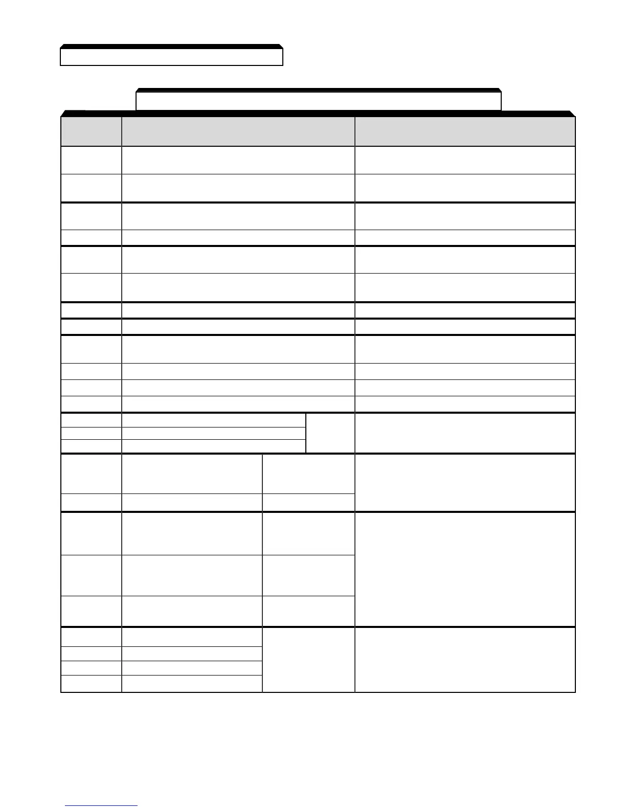
DATA FUNCTION DESCRIPTION*
S1 Multi-Function-Input 1 Factory setting is " Forward Run/Stop " (1).
(Forward run when closed, stop when open)
S2 Multi-Function-Input 2 Factory setting is " Reverse Run/Stop " (1).
(Reverse Run when closed, stop when open)
S3 Multi-Function-Input 3 Factory setting is " External Fault (NO contact)
input " (1)
S4 Multi-Function-Input 4 Factory setting is " Fault Reset " (1)
S5 Multi-Function-Input 5 Factory setting is " Multi-step Speed
Reference 1 " (1)
S6 Multi-Function-Input 6 Factory setting is " Multi-step Speed
Reference 2 " (1)
S7 Multi-Function-Input 7 Factory setting is " Jog Reference" (1)
SC Sequence common for terminals S1-S7. Common terminal for sequence inputs
FS Frequency reference power supply +12 VDC
FR Frequency reference input 0 to +10V/100% (20K ohms) or 4-20 mA (250 Ω)
RP Frequency reference –Pulse Train input 30 KHz maximum pulse input
FC Frequency reference input common 0 V
MA Multi-function contact output – NO contact Factory Contact capacity:
MB Multi-function contact output – NC contact Setting 250 Vac at 1A or below
MC Multi-function contact output – Common is " Fault " 30 Vdc at 1A or below
AM Multi-function analog monitor (+) Factory setting is
" Output frequency "
0-10V = 0-100% Monitor output: 0 to +10V; 2 mA maximum.
AC Analog monitor common 0 V
P1 Multi-Function Open Factory setting is
Collector Output 1 " Drive Running "
Photocoupler output:
P2 Multi-Function Open Factory setting is
48 VDC; 50 mA or less.
Collector Output 2 " Speed Agree "
PC Multi-Function Open 0 V
Collector Output common
R+ Receive input (+) MODBUS
R– Receive input (–) communication RS-485/422 MODBUS protocol,
S+ Send output (+) RS-485 or RS-422. 19.2 kps max.
S– Send output (–)
Table 1-3. Terminal Functions and Signals of Control Circuit
NOTES:
1. These inputs have factory settings based on 2-wire reset. For 3-wire reset definitions, see Figure 1-6.
Continued
1.4 ELECTRICAL INSTALLATION