5 Deployment I/O periphery
5.1 Overview
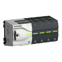
n On this CPU the connectors for digital respectively analog signal and T
echnological
functions are combined in a one casing.
n The project engineering happens in the Siemens SIMATIC Manager as Siemens CPU
314C-2 PN/DP (314-6EH04-0AB0 V3.3). Here the CPU M13-CCF0000 is parameter-
ized via the ‘Properties’ dialog of the Siemens CPU 314C-2 PN/DP
(314-6EH04-0AB0 V3.3).
n For parametrization of the digital I/O periphery and the technological functions the
corresponding sub modules of the CPU 314C-2 PN/DP (314-6EH04-0AB0 V3.3) is to
be used.
n The controlling of the operating modes of the technological functions happens by
means of handling blocks of the user program.
n The integrated I/Os of the CPU may be used for technological functions
or as
standard periphery.
n Technological functions and standard periphery may be used simultaneously with
appropriate hardware.
n Read access to inputs used by technological functions is possible.
n Write access to used outputs is not possible.
n
–
AI 2xUx12Bit (0 ... 10V)
– The analog channels of the module are not isolated to the electronic power
supply.
– The analog part has no status indication
Ä
Chapter 5.3 ‘Analog input’ on page 87
n
– DI 16xDC 24V
– Interrupt functions parameterizable
– Status indication via LEDs
Ä
Chapter 5.4 ‘Digital input’ on page 90
n
– DO 12xDC 24V, 0.5A
– Status indication via LEDs
Ä
Chapter 5.5 ‘Digital output’ on page 94
n
Ä
Chapter 5.6 ‘Counting’ on page 96
– 4 channels
– Count once
– Count continuously
– Count Periodically
– Control by the user program (SFB 47)
n
Ä
Chapter 5.7 ‘Frequency measurement’ on page 117
– 4 channels
– Control by the user program (SFB 48)
n
Ä
Chapter 5.8 ‘Pulse width modulation - PWM’ on page 123
– 2 channels
– Control by the user program (SFB 49)
Project engineering and
parametrization
I/O periphery
Technological functions
VIPA System MICRO
Deployment I/O periphery
Overview
HB400 | CPU | M13-CCF0000 | en | 16-47 86

 Loading...