User Guide for the VC400 Video Conferencing System
26
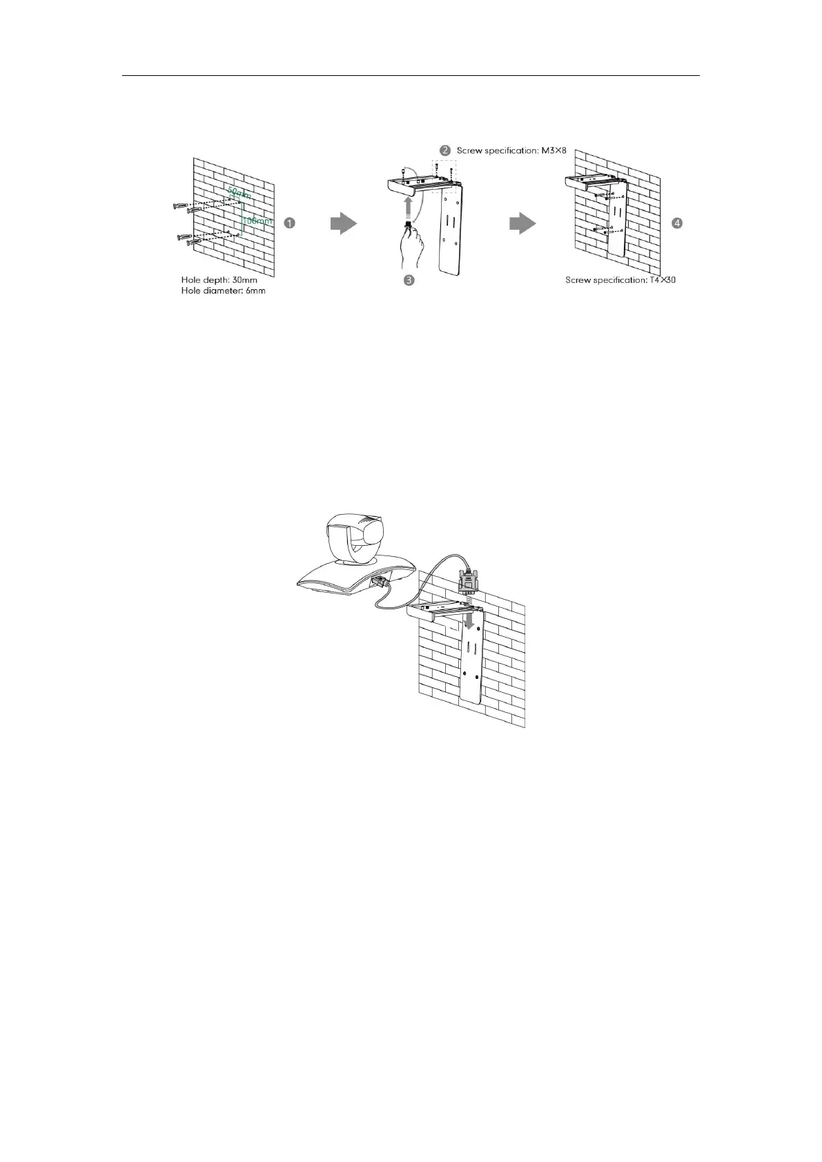
Do the following:
1. Punch holes in the wall and then insert the expansion bolts.
Installation location of the expansion bolts and punching requirement are shown above.
2. Lock the L-bracket with the M3×8 screws.
3. Adjust the screws position and manually lock them.
4. Lock the L-bracket to the wall with T4×30 screws.
5. Connect one end of the DVI cable to the camera and put the other end of the cable
through the L-bracket.
 Loading...