17-10
IM CW240E
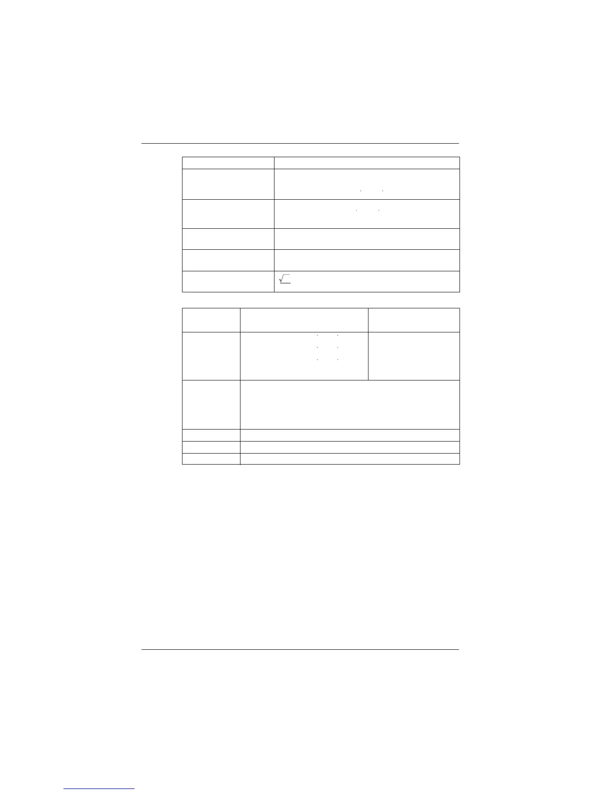
Measurement Item 3 Phase 3 Wire 2 Current
Voltage RMS Value
U1n
U2n(
Calculated as
U2
u3(t) )
U3n (
Calculated as
U3
u1(t)u3(t) )
Current RMS Value
Electric Power
Pn
P1nP3n
(P3n
U2rI3rU2iI3i
)
Qn Q1nQ3n
(
Q3n
U2rI3rU2iI3i)
Reactive Power
*1
Apparent Power
*1
I1n
I2n (
Calculated as
12 i 1(t)i 3(t) )
I3n
(S1nS3n)
2
3
Measurement Item
Wiring
3 Phase 3 Wire 3 Current 3 Phase 4 Wire
Voltage RMS Value
U1n (Calculated asU1
u1(t)
u2(t))
U2n(
Calculated asU2
u2(t)
u3(t))
U3n(
Calculated asU3
u3(t)
u1(t) )
u
n
(t):
Phase voltage from hypothetical midpoint
U1n
U2n
U3n
Phase voltage
Current RMS Value
I1n
I2n
I3n
I4n
(When using 4 current)
Electric Power
Pn
P1n
P2n
P3n
Reactive Power
*1
Qn
Q1n
Q2n
Q3n
Apparent Power
*1
Sn
S1n
S2n
S3n
By performing FFT operation on the 128 sample data that was taken in, nth order harmonics are
broken down into elements as follows.
nth Order Harmonic Voltage RMS Value
Un : (Unr, Uni)
nth Order Harmonic Current RMS Value Un : (Inr, Ini)
n : order
Unr, Inr : real number elements after FFT operation
Uni, Ini : imaginary number elements after FFT operation
P1n, P2n, P3n : active power (each element of the nth order)
Q1n, Q2n, Q3n : reactive power (each element of the nth order)
um(t), um(t) : vector
RMS Value Phase Angle: phase angle of the nth order harmonic element for the fundamental
wave element of the input signal
Electric Power Value Phase Angle:
phase of the current of the nth order for the voltage of the nth order
*1: Internal operation for use in power factor electric power phase angle and power factor
computation.
17.1 CW 240 Specifications

 Loading...


