1-1
Component Names and Functions
IM 710105-03E
1
Chapter 1 Component Names and Functions
1.1 Front Panel and Rear Panel
Front Panel
GO / NO-GO
43
LOGIC
21
M
1 / 20 pF 150 Vrms
50
5
Vrms,
10
Vpk
DLM2054
2.5GS/s 500MHz
MIXED SIGNAL OSCILLOSCOPE
PRINT
FILE
UTILITY
CLEAR
TRACE
SETUP
M
MENU
SNAP
SHOT
CURSOR MEASURE ANALYSIS
MATH/REF
DISPLAY
ACQUIRE
RUN/STOP
VERTICAL
POSITION
HORIZONTAL
POSITION
TRIGGER
FFT
LEVEL
TRIG’D
PUSH
PUSH
50%
0 s
50%
EDGE
ENHANCED
MODE
B TRIG
ACTION
GO / NO-GO
PUSH
0DIV
SCALE
PUSH
FINE
TIME/DIV
ZOOM
PUSH
FINE
ZOOM1 ZOOM2
SEARCH
SERLAL BUS
43
LOGIC
21
1 / 20 pF 150 Vrms
50
5
Vrms,
10
Vpk
X - Y
AUTO
DEFAULT
1
2
3
4
LOGIC
SHIFT
DELAY
ESC
SINGLE
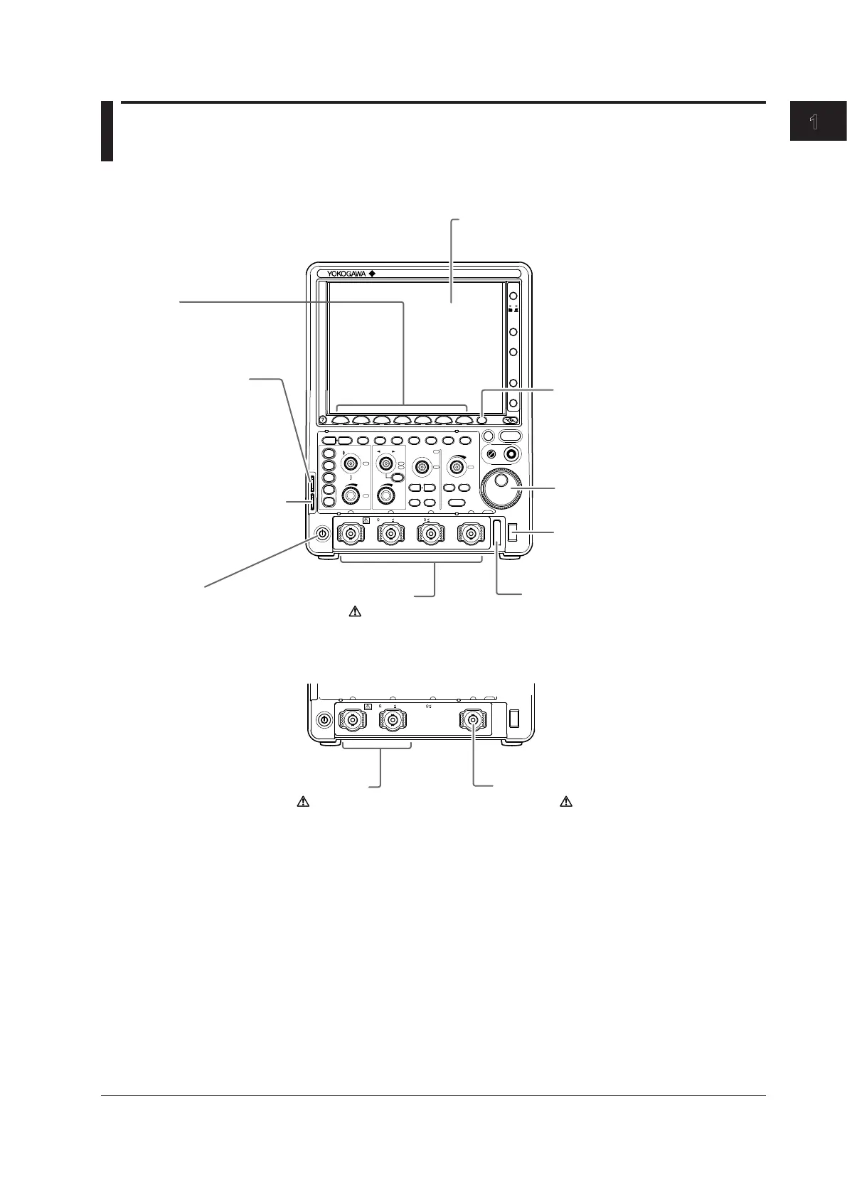
Soft keys
Use the soft keys to select items
on the soft key menus that
appear during configuration.
Jog shuttle
Use the jog shuttle to change
values and move cursors.
ESC key
Use this key to clear
soft key menus and
pop-up menus.
USB port for peripherals
Use this port to connect a USB
printer, storage device, keyboard,
or mouse.
Signal input terminals - probe
interface terminal
Connect probes to these terminals to
observe analog signals. → Section 2.4
Functional ground terminal
Connect a ground wire to this
terminal when correcting a probe
phase.
Power switch
→
Section 2.3
Probe compensation
signal output terminal
(1 kHz/1 Vp-p)
Transmits phase compensation
signals for probes.
Phase correction procedure
→ Section 2.5
Signal input terminal - logic
signal input port
Connect a logic probe to this terminal to
observe logic signals. This terminal is
available on 4-channel models without
the /LN option. → Section 2.6
External trigger signal input
terminal
Connect an external trigger signal
input probe to this terminal to take
measurements using an external
signal.
DLM2022, DLM2032, and DLM2052
Signal input terminals - probe
interface terminal
Connect probes to these terminals to
observe analog signals. → Section 2.4
Description of the displayed
contents → Section 1.3
DLM2024, DLM2034, and DLM2054

 Loading...


