<7. COMMISSIONING OF SC (Conductivity)>
7-7
IM 12A01A02-01E 8th Edition : Oct. 01, 2015-00
The output of the selected process parameter is shown as a bar on the bottom of the Main
display or the Home display. And its parameter symbol (for example, Conduct1-TC1 or Diff-
Cond-TC1) is shown above the bar, too. When a selected process parameter is displayed as a
measurement value, the top left number or character is turned to be white number or character
on black background (for example, or ). (Refer to the section 1.2.)
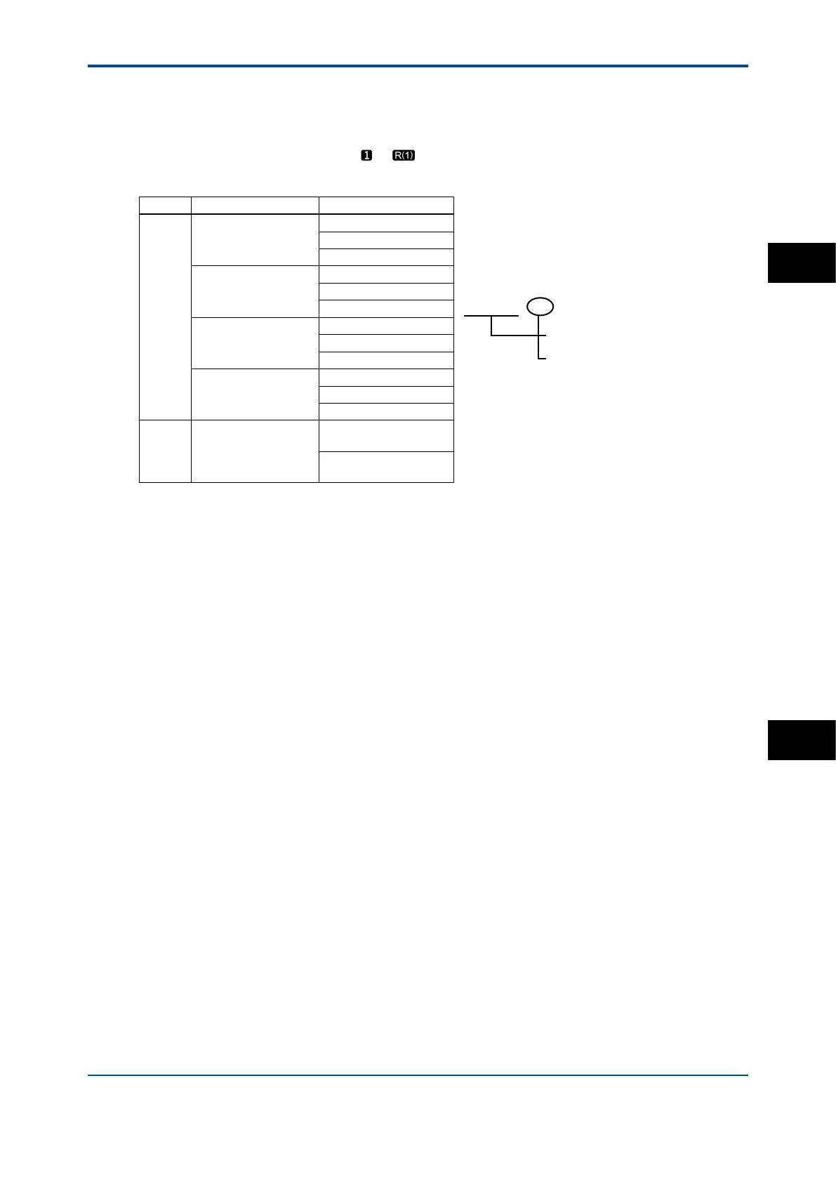
Table 7.2 List of Process Parameters
Sensor Measurement Process Parameters
1 or 2
Conductiivity
Conduct1 (2)-TC1
Conduct1 - TC1 :
Conductivity of sensor 1
Temperature compensation 1
Select the temperature compensation
method is section 7.1.4.
Temperature1 (2)
Conduct1 (2)-TC2
Resistivity
Resistivity1 (2)-TC1
Temperature1 (2)
Resistivity1 (2)-TC2
Concentration
Conduct1 (2)-TC1
Temperature1 (2)
Concent1 (2)-TC2
Conduct. + Concentr.
Conduct1 (2)-TC1
Temperature1 (2)
Concent1 (2)-TC2
2
Conductiivity
Resistivity
Concentration
Conduct. + Concentr.
Calculated
Redundant
Calculated data and Redundant system are available when two modules are installed on
the instrument. And, these functions are available when the “Conductivity” (or the parameter
including conductivity) or the “Resistivity” is selected on the “Measurement” type setting. The
parameter for the 1st module and the 2nd module should be the same. For wrong selection, an
error is given.
When the process parameter is set at “Calculated” of “Redundant”, don’t change the
“Measurement” type. If it is changed, the process parameter will go back to the default.
<Calculated>
For details, see section 7.7.
<Redundant >
On the Redundant system, when a sensor (Sensor 1) of the 1st module fails, the output is
automatically switched to the output of the 2nd module.
After repairing the Sensor 1, manual reset of redundant system is necessary to return to the
output of 1st module from the output of the 2nd module.
SC
7
 Loading...


