<Appendix 2 For SC (Conductivity)>
App.2-11
IM 12A01A02-01E 8th Edition : Oct. 01, 2015-00
FLXA202/FLXA21 is programmed with the following table of conductivity of Potassium Chloride
(KCl) solutions at 25°C. This is used in the Automatic Cell Constant setting calibration feature.
(See chapter 9 on calibration) The table is derived from the Standards laid down in “International
Recommendation No. 56 of the Organisation Internationale de Métrologie Legale”.
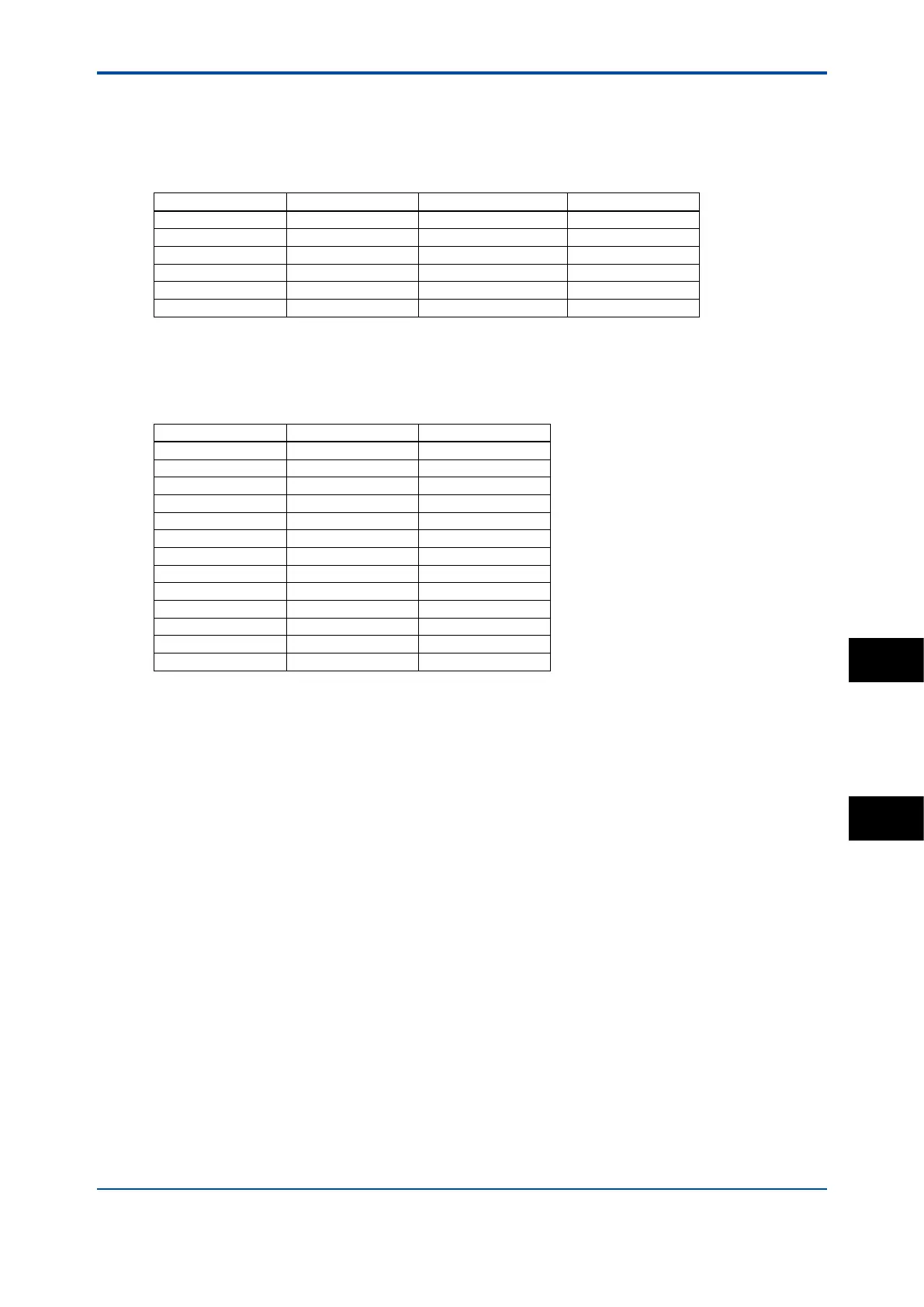
Table 4 KCl values at 25 °C
Standard solution mol/l mg KCl/kg of solution Conductivity
1.000 M KCl 1.0 71135.2 111.31 mS/cm
0.100 M KCl 0.1 7419.13 12.852 mS/cm
0.010 M KCl 0.01 745.263 1.4083 mS/cm
0.005 M KCl 0.005 373.29 0.7182 mS/cm
0.002 M KCl 0.002 149.32 0.2916 mS/cm
0.001 M KCl 0.001 74.66 0.1469 mS/cm
If it is more convenient, the user may make solutions from Sodium Chloride (NaCl or common
table salt) with the help of the following relationship table. This table is derived from the IEC norm
60746-3.
Table 5 NaCl values at 25 °C
Weight % mg/kg Conductivity
0.001 10 21.4 µS/cm
0.003 30 64.0 µS/cm
0.005 50 106 µS/cm
0.01 100 210 µS/cm
0.03 300 617 µS/cm
0.05 500 1.03 mS/cm
0.1 1000 1.99 mS/cm
0.3 3000 5.69 mS/cm
0.5 5000 9.48 mS/cm
1 10000 17.6 mS/cm
3 30000 48.6 mS/cm
5 50000 81.0 mS/cm
10 100000 140 mS/cm
For resistivity measurement the standard resistivity units of the calibration solution can be
calculated as follows:
R = 1000/G (kΩ•cm if G = µS/cm)
Example: 0.001% weight R = 1000/21.4 = 46.7 kΩ•cm
n Monitoring of Puried Water and WFI according to USP<645>
First published in the USP23 (The United States Pharmacopeia, ed. 23), the USP <645>
describes a procedure of measuring the conductivity of Puried Water and WFI (Water for
Injection) instead of the previous complicated monitoring procedure. This procedure consists
of three stages for measuring the conductivity of Puried Water and WFI. On the stage 1,
rstly the temperature of the water and the non-temperature-compensated conductivity of the
water are measured, and this conductivity is compared with the limit conductivity value of the
corresponding temperature directed by USP<645>. (Refer to Figure 3.) If the conductivity is
higher than the limit value, the procedure will proceed to the stage 2.
The FLXA202/FLXA21 has the limit values of USP<645> built in the rmware. When the error
conguration is set for this monitoring, the FLXA202/FLXA21 checks the non-temperature-
compensated conductivity with the limit value. If the conductivity is higher than the limit value, an
error will be generated. A safety margin to the limit value can be set on the FLXA202/FLXA21 to
generate an error below limit value. (Refer to the section 7.3.)
When the safety margin is set at 20%, for example, an error will be generated when the non-
temperature-compensated conductivity goes higher than the 80% of the limit value at all
temperatures. For example, if the temperature is 64 ºC. and the safety margin is set at 20%,
then an error will be generated at 0.8 x 2.2 μS/cm. = 1.76 μS/cm. (2.2 μS/cm is the USP<645>
limit value at 64ºC). In resistivity mode, an error will be generated at an non-temperature-
compensated resistivity of 0.568 MΩ (=1/1.76 μS/cm).
App.
SC
 Loading...


