<Appendix 3 For ISC (Inductive Conductivity)>
App.3-11
IM 12A01A02-01E 8th Edition : Oct. 01, 2015-00
The conductance (1/R) is proportional to the specic conductivity and a constant factor that
is determined by the geometry of the sensor (length divided by surface area of the hole in the
toroid) and the installation of the sensor.
There are 2 toroids mounted in the “dough nut” shaped sensor. The liquid also ows through the
second toroid and therefore the liquid turn can be considered as a primary wind ing of the second
ring transformer.
The current in the liquid will create a magnetic eld in the second toroid. The induced voltage
being the result of this magnetic eld can be measured as an output.
The output voltage of this “receive coil” is therefore proportional to the specic con ductivity of the
process liquid.
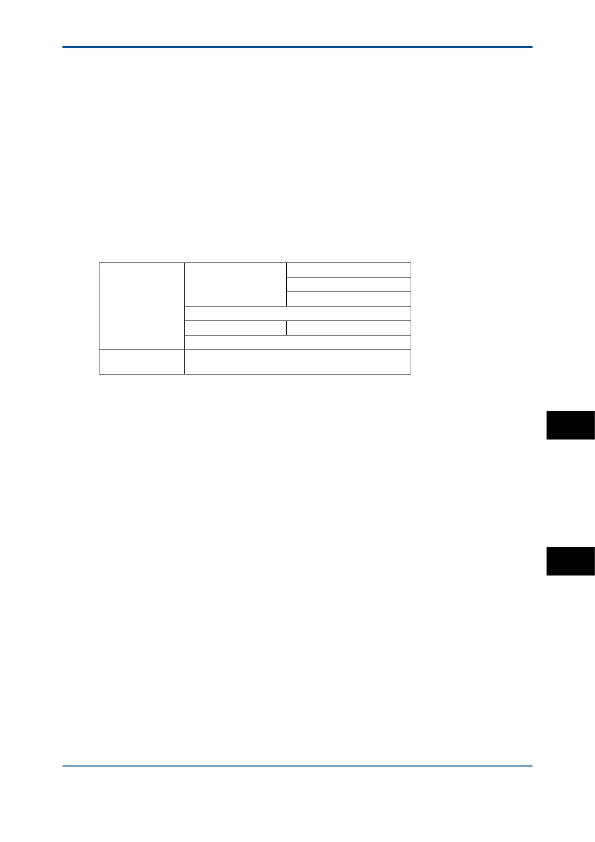
n Changing the settings
If any setting is accidentally changed, values to the right of the relevant arrow in Table 6 are all
initialized.
Table 6 Parameters that initialize other values
Measurement -> Output: Process
parameter ->
Linear: 0% value, 100% value
Table
Communication: HART: PV
Display setup: Main display
Trend Graph Screen -> Y-axis (low, high)
Communication: HART
Congure sensor:
Measuring unit ->
Display setup: Main display: unit
App.
ISC
 Loading...


