Quick Reference Instruction Manual for Spare
Sensor replacement
Wiring
26 / 76
IM01U10A01-00EN-R, 1
st
edition, 2019-12-09
Installation of fire
retardant connecting
cable option Y
␣␣␣
1 2
3
D+
D–
S1+
S1–
S2+
S2–
TP1
TP2
TP3
D+
D–
S1+
S1–
S2+
S2–
TP1
TP2
TP3
COM
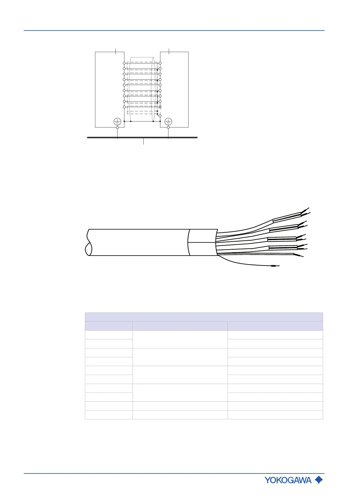
Fig.16: Transmitter and sensor interconnection diagram
1 Sensor
2 Transmitter
3 Potential equalization system
Fig.17: Terminated fire retardant connecting cable Y␣␣␣, transmitter side
Connection scheme of fire retardant connecting cable option Y␣␣␣
Tab.4: Version Y␣␣␣
Y
␣␣␣
-cable
Signal Conductor pair number
1)
Conductor colour
D+
1
white
D- blue
S1+
2
white
S1- blue
S2+
3
white
S2- blue
TP1
4
white
TP2 blue
TP3 5 white
COM
2)
Shield wire
2)
–
1)
Conductor pair number refers to the numbers printed on the single conductors
2)
Present only at transmitter side
 Loading...


