Quick Reference Instruction Manual for Spare
Transmitter replacement
Wiring
64 / 76
IM01U10A01-00EN-R, 1
st
edition, 2019-12-09
P/Sout- or Sout-
P/Sout+ or Sout+
ROTAMASS
2
1
3
4
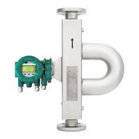
Fig.43: Passive status output connection P/Sout or Sout for solenoid valve circuit
① Relay
② Solenoid valve
③ Magnetic valve power supply
④ Protective diode
A relay must be connected in series to switch alternating voltage.
Passive pulse or
status output
P/Sout (NAMUR)
Output signals according to EN 60947-5-6 (previously NAMUR, worksheet NA001):
10kΩ
1kΩ
ROTAMASS
P/Sout+
P/Sout-
2
1
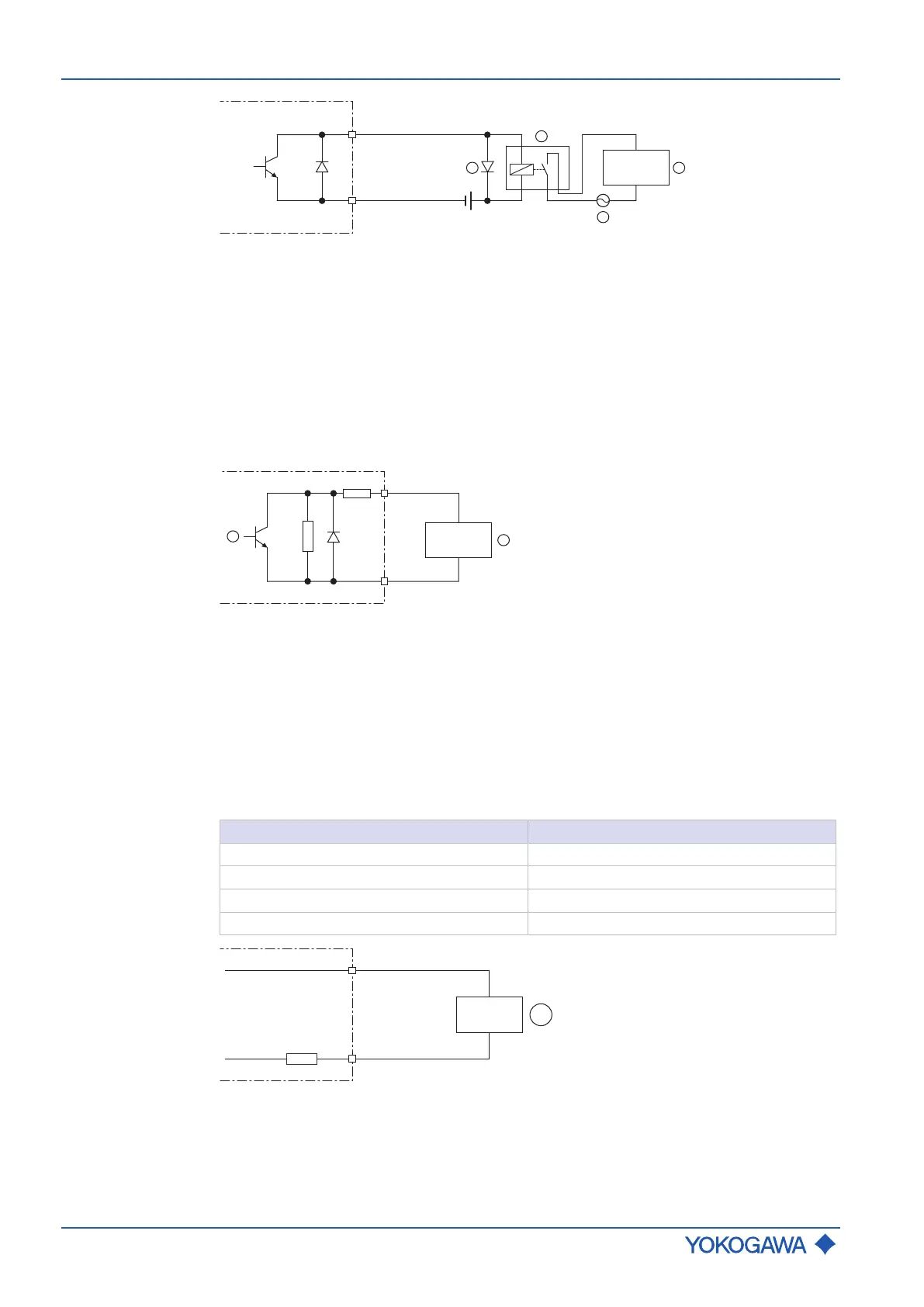
Fig.44: Passive pulse or status output with switching amplifier connected in series
① Passive pulse or status output
② Switching amplifier
Input signals
Active current
input lin
An individual analog power input is available for external analog devices.
The active current input lin is provided for connecting a two-wire transmitter with an out-
put signal of 4–20 mA.
Value
Nominal input current 4 – 20 mA
Maximum input current range 2.4 – 21.6 mA
Internal power supply 24 V
DC
±20 %
Internal load resistance Rotamass ≤ 160 Ω
Fig.45: Connection of external device with passive current output
① External passive current output device
 Loading...


