Wiring
Quick Reference Instruction Manual for Spare
Transmitter replacement
IM01U10A01-00EN-R, 1
st
edition, 2019-12-09
63 / 76
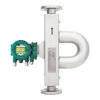
Active status
output P/Sout
Since this is a transistor contact, maximum allowed current as well as polarity and level of
output voltage must be observed during wiring.
Value
Load resistance > 1 kΩ
Internal power supply 24 V
DC
±20 %
P/Sout+
P/Sout-
24 V
0 V
ROTAMASS
1
Fig.40: Active status output connection P/Sout
① External device with load resistance
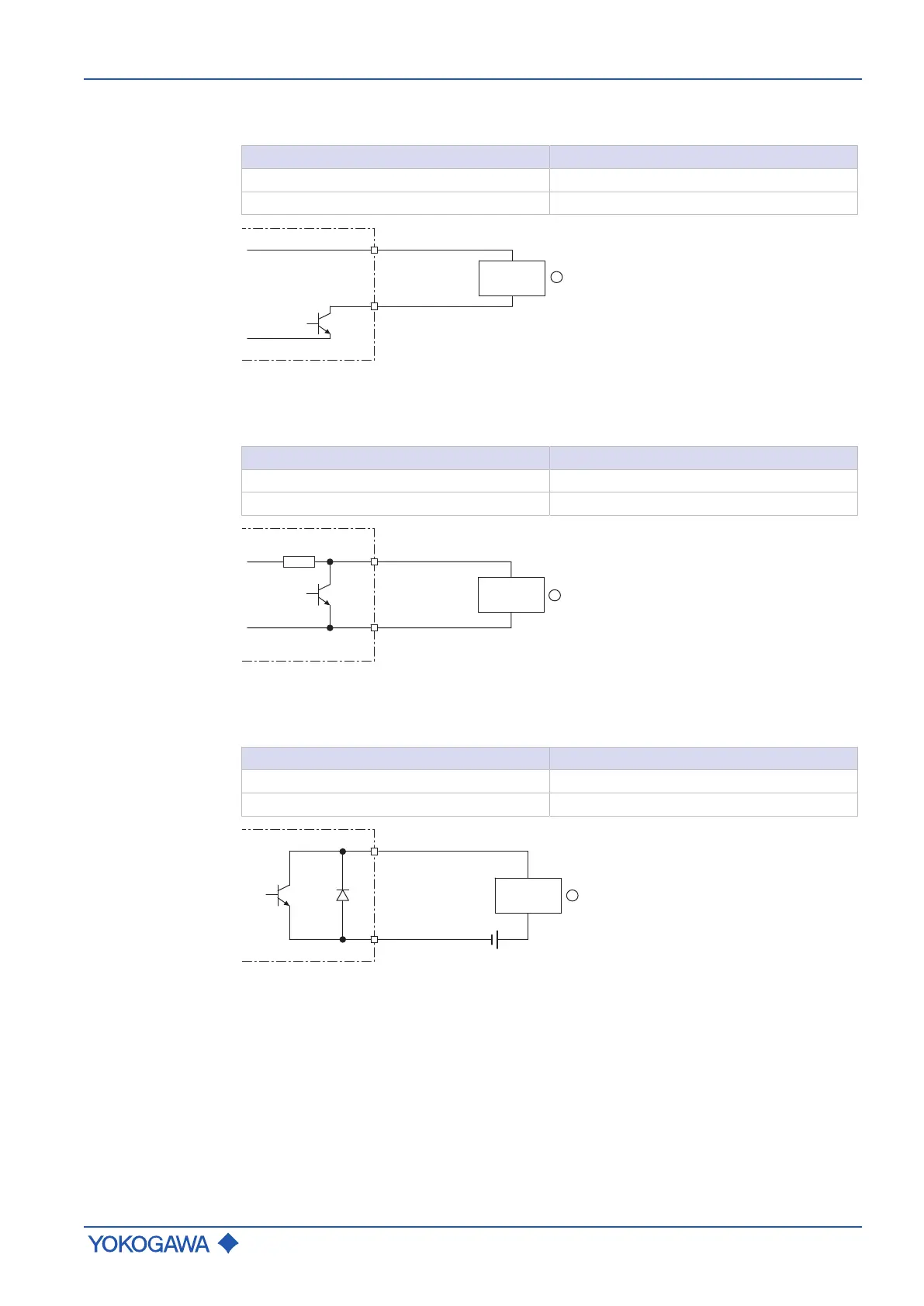
Active status
output P/Sout
with internal
pull-up resistor
Value
Internal pull-up resistor 2.2 kΩ
Internal power supply 24 V
DC
±20 %
P/Sout+
P/Sout-
24 V
0 V
ROTAMASS
1
Fig.41: Active status output P/Sout with internal pull-up resistor
① External device
Passive status
output P/Sout
or Sout
Value
Output current ≤ 200 mA
Power supply ≤ 30 V
DC
P/Sout+ or Sout+
P/Sout- or Sout-
ROTAMASS
1
Fig.42: Passive status output connection P/Sout or Sout
① External device
 Loading...


