16-3
IM WT1801-01EN
Data Capturing Interval
The interval at which data is captured varies as shown below depending on how External Sync is set.
• When External Sync is set to OFF: 5 ms
• When External Sync is set to ON: The interval at which data is captured depends on the sync signal that is
applied to the external start signal I/O (MEAS START) connector. The WT1800 can sync with a signal whose
period is 1 ms to 100 ms.
Display Update Rate
The display update rate is approximately 1 s.
Numeric Data Display
The numeric data for each measurement function that was last measured within the display update interval is
displayed.
You cannot make individual changes to the displayed measurement functions. Use the PAGE UP and PAGE
DOWN keys to change the display.
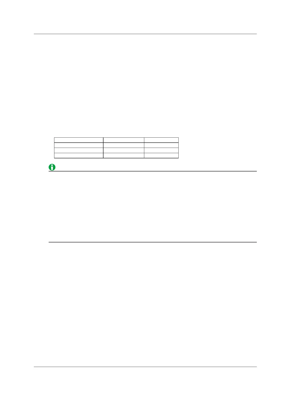
The number of pages varies as indicated below depending on the installed options.
Motor Evaluation Function External Signal Input Number of Pages
Not installed Not installed 2 pages
Installed Not installed 4 pages
Not installed Installed 4 pages
• If the measured value exceeds 300%, “-OL-” (for over range) is displayed for U or I. When you are
measuring with the highest measurement range, if the measured value exceeds 140%, “-OL-” (for over
range) is displayed for U or I.
•
If the measured value for the voltage or current is over range,
“-OL-” (for over range) is displayed for P.
• “-OL-” (for over range) is displayed for UΣ if even one of the measured voltage values for an input element
in a single wiring unit is over range. The same is true for IΣ and PΣ.
• UΣ and IΣ are displayed as zero when they are the following percentage of the maximum voltage range or
current range out of the input elements assigned to the same wiring unit.
• When the Crest Factor Is Set to CF3
0.3% or less for Urms and Irms. 2% or less for Umn, Urmn, Imn, and Irmn.
•
When the Crest Factor Is Set to CF6
0.6% or less for Urms and Irms. 4% or less for Umn, Urmn, Imn, and Irmn.
Fundamental Measurement Conditions
All the settings for the fundamental measurement conditions for high speed data capturing are the same as
those for normal measurement.
However, the following limitations apply to the wiring system and line filter.
Wiring System during High Speed Data Capturing
•
When the wiring syste
m is set to one of the following settings, you can measure the voltage (U), current (I),
and power (P).
•
1P2W
: Single-phase, two-wire system (DC signal)
• 3P4W: Three-phase, four-wire system
• 3P3W (3V3A): Three-voltage, three-current method
• When the wiring system is set to one of the following settings, the voltage (UΣ), current (IΣ), and power (PΣ)
for the wiring unit are not measured and are displayed as "-------" (no data). When the wiring system is being
set or high speed data capturing has been started, an error message appears.
• 1P3W
: Single-phase, three-wire system
• 3P3W: Three-phase, three-wire system
16 High Speed Data Capturing

 Loading...


