22-10
IM WT1801-01EN
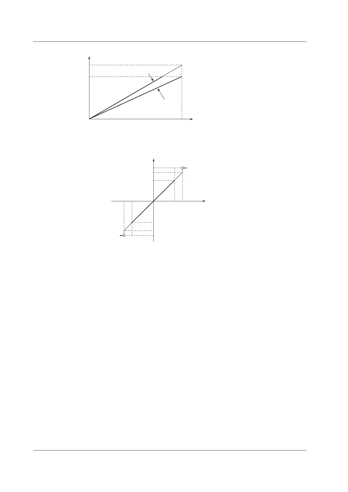
Integrated Values
D/A output
Approx. 7.0 V
5.0 V
0
Integration time
t
0
At 140% of the rated input
At the rated input
t0: The rated time of integrated D/A output in manual integration mode.
The timer time in normal or continuous integration mode.
Other Items
140% Approx. 7.0 V
100% 5.0 V
0% 0 V
–100% –5.0 V
–140% Approx. –7.0 V
D/A output
Approx. 7.5 V
Approx. 7.0 V
5.0 V
0
–5.0 V
−
100
100
−
140
140
Approx. –7.0 V
Approx. –7.5 V
Displayed
value (%)
Output
Displayed
value
• The outputs for λ, Φ, EaU, and EaI do not exceed ±5 V. When the display format of Φ is set to 360 degrees,
the output for Φ ranges from 0 V to +5 V. When the display format of Φ is set to 180 degrees (lagging 180°
to leading 180°), the output for Φ ranges from –5 V to +5 V. However, when an error occurs, the output is
approximately 7.5 V. Only the outputs for U–pk and I–pk are approximately –7.5 V when an error occurs.
•
The outputs for η
1
to η
4
, Uhdf, Ihdf, Phdf, Uthd, Ithd, Pthd, Uthf, Ithf, hvf, hcf, and Slip
*
are +5 V at 100%.
• The outputs for Utif and Itif are + 5 V at 100.
• The output for an analog torque signal is +5 V when the torque reaches the value of the input range × the
torque scaling factor × the input signal slope (this is the rated value).
1
For example, when the input range is 10 V,
if the scaling factor is set to 1 N•m of torque per 1 V of input voltage, the output is +5 V when the torque is 10
N•m.
•
The output for an analog rotating speed signal is +5 V when th
e rotating speed reaches the value of the input
range × the revolution scaling factor × the input signal slope (this is the rated value).
1
For example, when the
input range is 10 V, if the scaling factor is set to 100 rpm per 1 V of input voltage, the output is + 5 V when the
rotating speed is 1000 rpm.
•
The output for a pulse rotating speed signal is –5 V when the r
otating speed reaches the value specified for
Pulse Range Upper × –1 (this is the rated value), and the output is +5 V when the rotating speed reaches the
value specified for Pulse RangeUpper.
1
• The output for a pulse torque signal is –5 V when the torque reaches the value specified for Pulse Range
Upper × –1 (this is the rated value), and the output is +5 V when the torque reaches the value specified for
Pulse RangeUpper.
1
• The output for SyncSp is +5 V when SyncSp is at the rated value for Speed.
1
• The output for Pm is +5 V when Pm reaches the motor output value obtained from the rated values for the
torque and rotating speed.
1
• The output for Aux1 or Aux2 is +5 V when Aux1 or Aux2 reaches the value of the input range × the scaling
factor for Aux1 or Aux2 × the input signal slope (this is the rated value).
2
1 Speed and torque waveforms are available on models with the motor evaluation option.
2 Aux1 and Aux2 waveforms are available on models with the auxiliary input option.
22 Utility

 Loading...


