<12. Troubleshooting>
12-7
IM 11M12A01-04E 11th Edition : Jul. 19, 2017-00
<Search for cause of failure and Take measures>
This equipment can be used at ambient temperatures up to 55°C. If the ambient temperatures
may exceed the limits, take appropriate measures such as applying heat insulating material to
the furnace walls, and adding a sun shield to keep out direct sunlight.
If this alarm occurs even when the ambient temperature is under 55°C, the electronics may be
defective. Contact your local Yokogawa service or sales representative.
l Alarm 11: Thermocouple Voltage Alarm
This alarm is generated when the emf (voltage) of thermocouple falls below -5 mV (about
-170°C) or exceeds 42.1 mV (about 1020°C).
(1) A failure of the thermocouple at the detector occurred.
(2) A failure of the electrical circuits occurred.
<Search for cause of failure and Take measures>
(1) Turn off the power to the analyzer.
(2) Remove the probe from the analyzer. Also remove all the connectors between the converter
and probe. Measure the resistance of the heater wire (yellow wire) from the probe as
indicated in Figure 12.5. The heater assembly is normal if the resistance is lower than about
90Ω. If the resistance is higher than that value, the heater assembly may be defective. In
this case, replace the heater assembly (refer to Section 11.1.3, “Replacement of the Heater
Assembly”).
F12.2E.ai
Multimeter
(Ω)
Heater wire
Figure 12.5
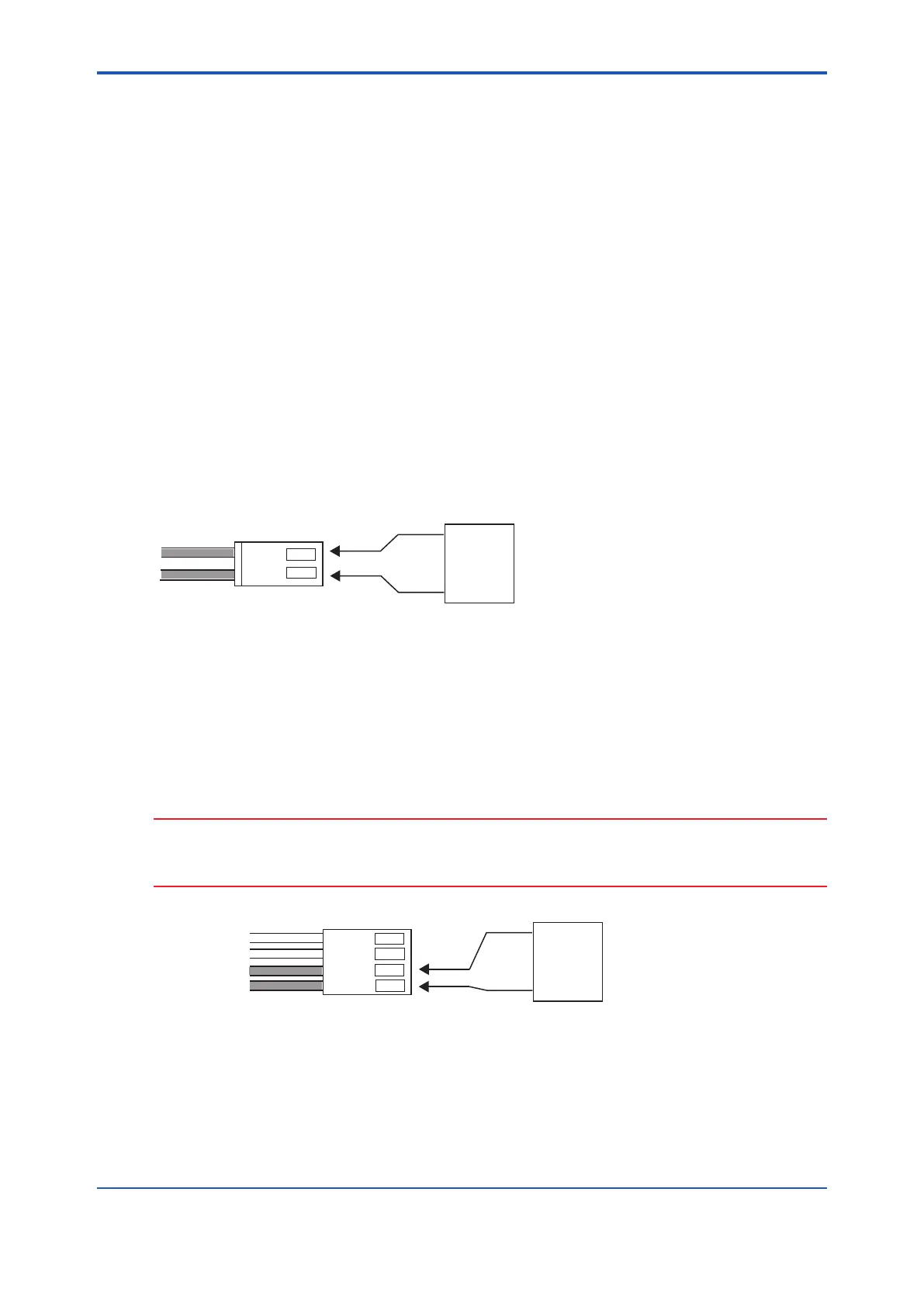
(3) Next, check the resistance of the thermocouple from the probe. Use a multimeter to
measure the thermocouple resistance between terminal 3 (red cable connected) and
terminal 4 (white cable connected) as indicated in Figure 12.6.
The thermocouple is normal if the resistance is 5Ω or less. If the value is higher than 5Ω, the
thermocouple wire may be broken or about to break. In this case, replace the heater assembly
(refer to Section 11.1.3, “Replacement of the Heater Assembly”).
CAUTION
Measure the thermocouple resistance value after the difference between the probe tip
temperature and the ambient temperature decreases to 50°C or less. If the thermocouple
voltage is large, accurate measurement cannot be achieved.
F12.3E.ai
1
2
3
4
YEL
GRN
RED
WHT
Thermocouple
Multimeter
(Ω)
Figure 12.6
(4) If the inspection indicates that the thermocouple is normal, the electronics may be defective.
Consult your local Yokogawa service or sales representative.

 Loading...


