<4. Piping>
4-7
IM 11M12A01-04E 11th Edition : Jul. 19, 2017-00
CAUTION
• Use suitable cable glands to completely seal the detector. As far as possible do not stop the
instrument air ow, to prevent the sample gas from entering the detector and damaging the
zirconia cell.
• Connect the stop valve, which is at the calibration gas inlet, directly to the equipment.
If piping connections are made between the detector and the needle valve, condensation
will result inside the piping and cause the sensor to be damaged when the calibration gas is
introduced.
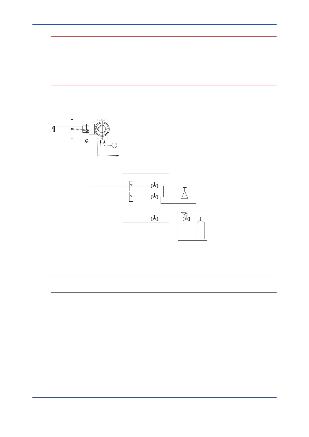
Figure 4.7 illustrates an example of System 2 using the analyzer with pressure compensation.
Supplying the air pressure (ow) may vary depending on the furnace pressure. It is
recommended to use a ow gauge and an air set meeting the furnace pressure.
~
ZR202G Integrated type Zirconia Oxygen Analyzer
with pressure compensation
F1.2E.ai
ZA8F flow setting unit
Reference gas
Calibration gas
Needle
valve
Flowmeter
Instrument air
Air Set
Pressure
regulator
Zero gas cylinder
Calibration gas unit case
Stop valve
or
Check valve
Span gas(Same as Zero gas calibration)
100 to 240 V AC
Contact input
Analog output, contact output
Digital output (HART)
Figure 4.7 Illustrates an example of System 2 using the analyzer with pressure compensation.
NOTE
When using the ZA8F Flow Setting Unit and the ZR20H Automatic Calibration Unit, please note
that the supplying airow (pressure) will vary depending on the furnace pressure.

 Loading...


