AF6ZP0CA – COMBIAC0 & ACE0 2uC – User Manual Page – 23/155
Inverter voltage 24 V 36/48 V 80 V
Logic low threshold
1.8 V 6 V 6 V
Logic high threshold
4.4 V 13.5 V 13.5 V
Voltage range
0 V ÷ 35 V 0 V ÷ 65 V 0 V ÷ 115 V
U For critical functions, when good diagnostics coverage is necessary, it is
recommended to use two digital inputs for plausibility check, for example
to use both normally open and normally closed contacts.
Protection
Each digital input has a 22 nF capacitor to -B for ESD protection.
Circuit
Input impedance of digital inputs in standard Zapi configurations are listed below.
Custom hardware may feature different impedance values.
Inverter voltage 24 V 36/48 V 80 V
Input impedance
4.5 k 14.5 k 30 k
4 Digital inputs DI1, DI2, DI5, DI6, DI7, DI8, and DI9 are normally configured to be
activated when closed to +B. Their behavior can be changed by special HW
configuration, as to be activated when closed to -B.
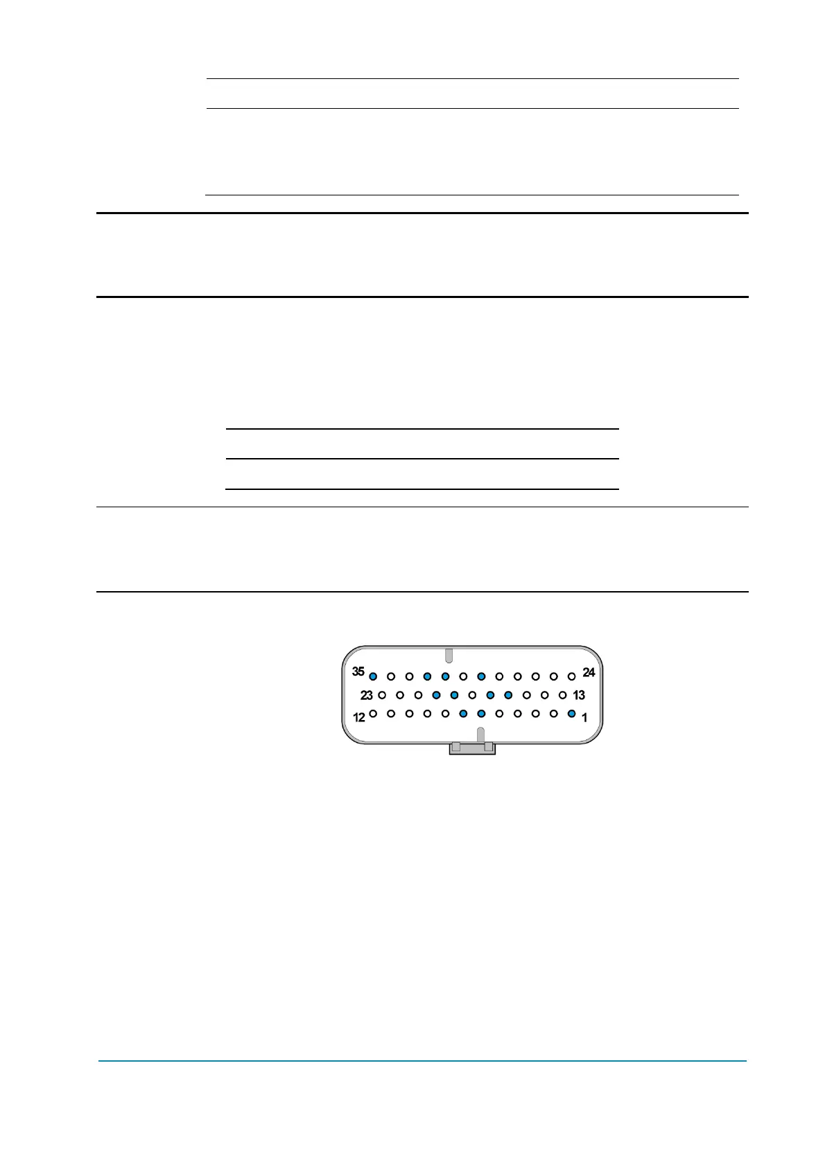
Connector position
A1, A6, A7, A16, A17, A19, A20, A29, A31, A32, A35.
Microswitches
- It is suggested that microswitches have a contact resistance lower than 0.1
and a leakage current lower than 100 µA.
- In full-load condition, the voltage between the key-switch contacts must be
lower than 0.1 V.
- If the microswitches to be adopted have different specifications, it is
suggested to discuss them with Zapi technicians prior to employ them.