AF6ZP0CA – COMBIAC0 & ACE0 2uC – User Manual Page – 21/155
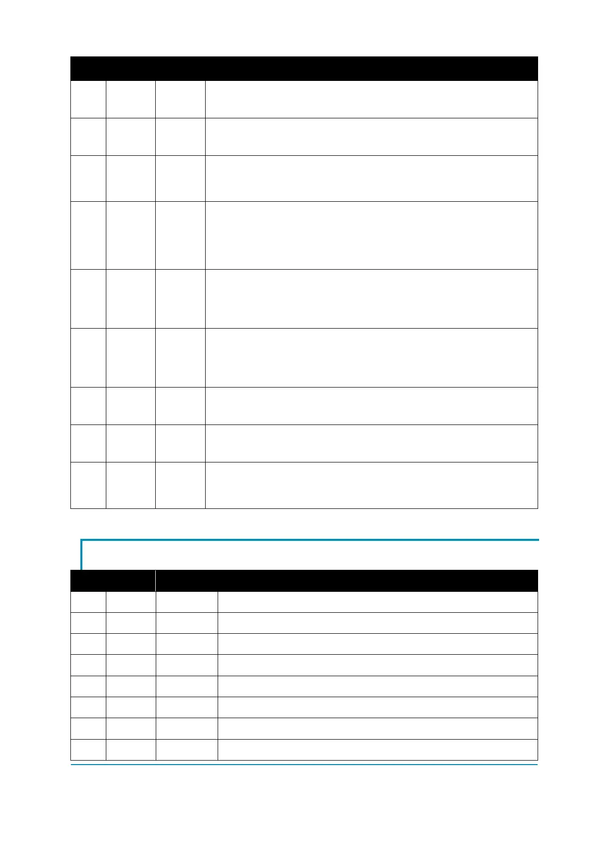
Pin Type Name Description
A27 Output CANL Low-level CAN bus line.
A28 Output CANH High-level CAN bus line.
A29 Input DI9
Digital input DI9.
The input is activated when the external switch is opened.
The default function is as LIFT DC CUTBACK input.
A30 Input CPOT2
Analog input for the lift/lower potentiometer.
If PEDAL BRK ANALOG = ON this input is used as analog brake
input.
If AUX POT. TYPE is different from 12; this input is used as
reference for the lowering proportional valve.
A31 Input DI4
Digital input DI4.
The input is activated when it is connected to +B.
The default function is as BW request. Closing this input truck
moves backward.
A32 Input DI3
Digital input DI3.
The input is activated when it is connected to +B.
The default function is as FW request. Closing this input truck
moves forward.
A33 Output EV3
Driving output for the PWM voltage-controlled electrovalve EV3
(driving to -B); 1 A maximum continuous current.
A34 Output EV4
Driving output of the on/off electrovalve EV4 (driving to -B); 1 A
maximum continuous current.
A35 Input DI7
Digital input DI7.
The input is activated when it is connected to +B.
The default function is as LIFT enable input.
4.3 Internal connector
Pin Type Name Description
1 - - Not used: it can be unconnected.
2 Input NCLRXD Negative serial reception.
3 Output PCLTXD Positive serial transmission.
4 Output NCLTXD Negative serial transmission.
5 Output GND Negative console power supply.
6 Output +12 Positive console power supply.
7 Input FLASH It must be connected to pin 8 for flashing the code.
8 Input FLASH It must be connected to pin 7 for flashing the code.