AF6ZP0CA – COMBIAC0 & ACE0 2uC – User Manual Page – 33/155
potentiometers is available on pin A8 in substitution of EV5 output.
Output voltage is configurable via hardware by internal jumper to +12V or +5V;
maximum output current is 100 mA.
4 Actual values for “+12V” and “+5V” are respectively 13.1 V ± 0.5 V and
5 V ± 0.3 V.
Protection
Analog supply output is protected against over current with a thermal shut down
and protected against accidental connection to +B with a diode.
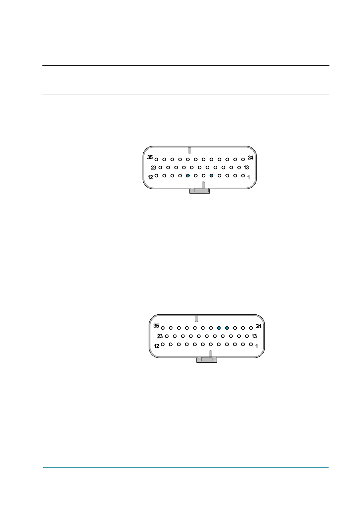
Connector position
GND A5, PPOT (+5/+12) A8.
4.4.13 CAN bus
CAN bus interface is available for communication with the controller, featuring:
Physical Interface according to ISO 11898-2.
Data rate can be 125, 250 or 500 kbit/s.
CAN driver is +5 V supplied and provides a rail to rail signal on the
differential output (CANH - CANL).
An internal 120 termination resistor can be built-in.
Common-mode filter (resistors and capacitor) is present.
Protection
CAN bus interface is protected against accidental connection to +B and -B and
ESD protected.
Connector position
CANL A27, CANH A28.
4 CAN-cabling shall use a pair of twisted wires for CANH and CANL wires.
The CAN wiring shall have a characteristic impedance of 120 Ω and both
physical ends of the CAN bus shall be terminated with 120 Ω between CANH and
CANL for best possible noise immunity.