AF6ZP0CA – COMBIAC0 & ACE0 2uC – User Manual Page – 41/155
U VERY IMPORTANT
Since the logic unit and the software must be set in the correct way by Zapi
lines, it is absolutely mandatory to specify in the commercial order the type
of Hall sensors used (in terms of supply voltage, output voltage and
number of pulses per revolution), their configuration in the d-axis rotor
orientation and their sequence around one turn.
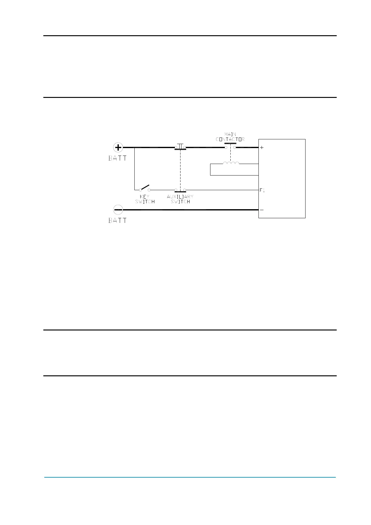
5.2.7 Connection of main contactor and key switch
- Main contactor and key switch can be connected as the following figure.
Connection of main contactor and key switch.
- The connection of the battery line switches must be carried out following
instructions from Zapi.
- If a mechanical battery line switch is installed, it is necessary that the key
supply to the inverter is open together with power battery line; if not, the
inverter may be damaged if the switch is opened during a regenerative
braking.
- An intrinsic protection is present against battery voltages above 140% of the
nominal one and against the key switching off before disconnecting the
battery power line.
5.2.8 Insulation of the truck frame
U As stated by EN-1175 “Safety of machinery – Industrial truck”, chapter 5.7,
“there shall be no electrical connection to the truck frame”. So the truck
frame has to be isolated from any electrical potential of the truck power
line.