AF6ZP0CA – COMBIAC0 & ACE0 2uC – User Manual Page – 27/155
Configurable output voltage, by means of two dedicated parameters for
pulling and holding stages.
4 PWM should only be used for inductive loads such as relays, contactors, motor
brakes or hydraulic valves.
4 PWM frequency can be changed by software. However, if a different PWM
frequency has to be used it is suggested to discuss it with Zapi technicians.
Protection
Protected against inductive discharge with internal freewheeling diode to the
positive supply pin (A10 or A1, depending on the hardware configuration) and
ESD protected by means of a suppressing device. Protected against reverse
polarity of the battery.
Built-in diagnostics:
- Overcurrent
- Driver shorted
- Driver open
- Coil open
Refer to chapter 10 more details about alarms.
4 Overcurrent protection is featured by hardware and it is shared with EB output.
4 MC output can only be a PWM voltage-controlled output. It cannot be used as a
current-controlled output.
U When driving an inductive load on PWM open-drain output, there must
always be a path for the current through a freewheeling diode. Do not
connect any switch or fuse in series with the diode.
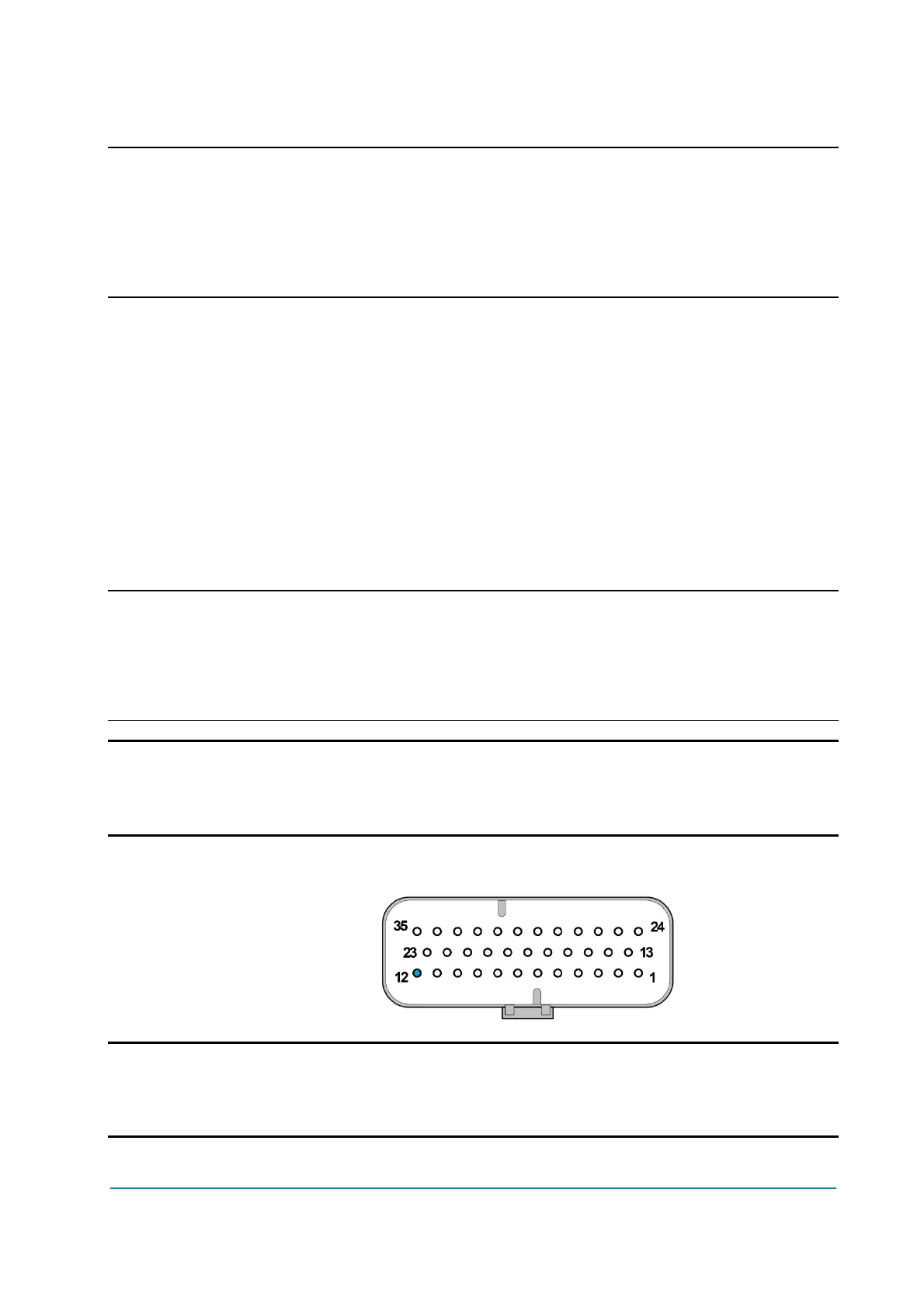
Connector position
A12.
U To protect the controller from overvoltage caused by an inductive load,
freewheeling diode to the positive supply pin (A10 or A1, depending on the
hardware configuration) is built-in.