AF6ZP0CA – COMBIAC0 & ACE0 2uC – User Manual Page – 37/155
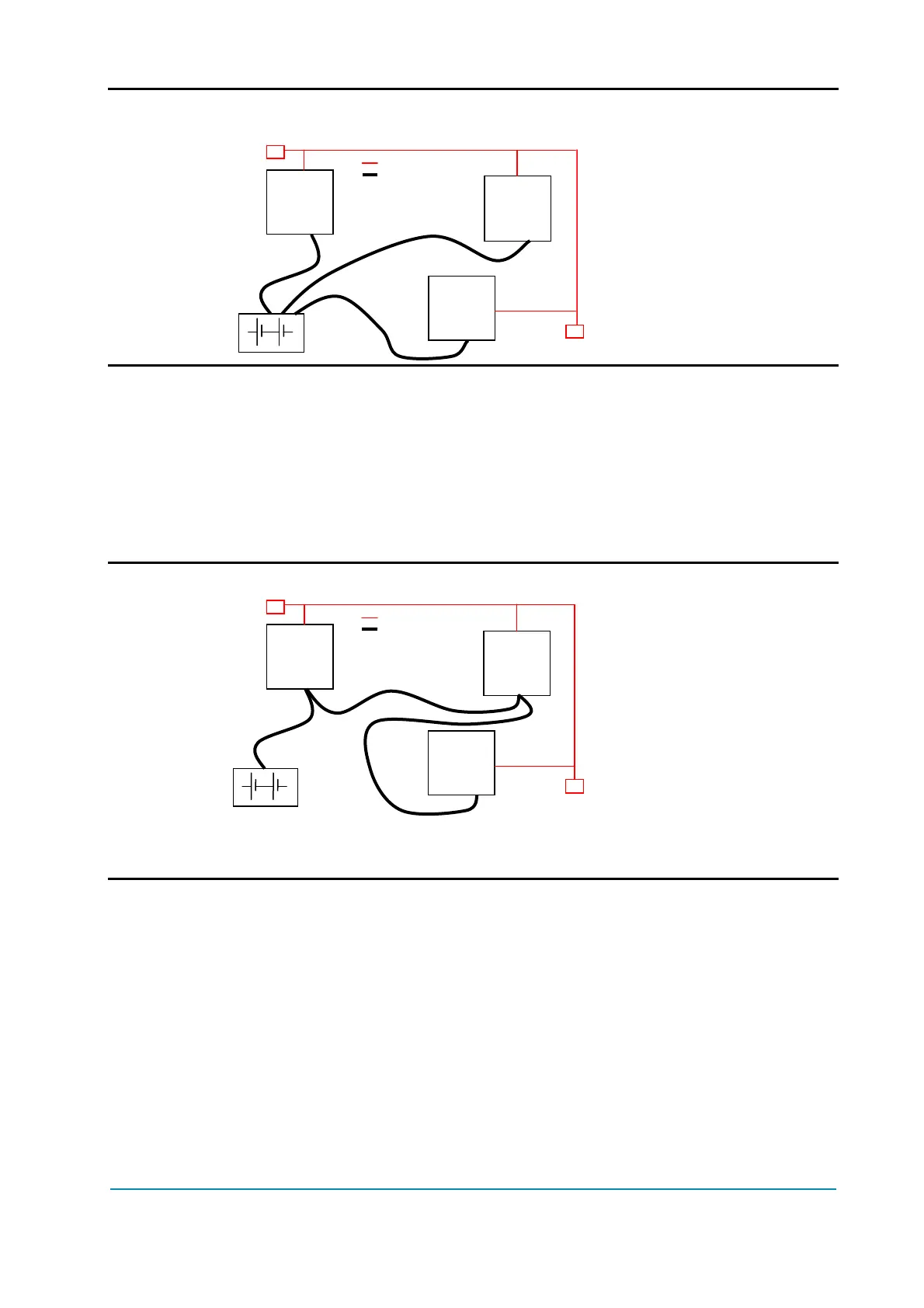
U Wrong Layout:
Red lines are CAN bus wires.
Black boxes are different modules, for example a traction controller, a pump
controller and a display connected via CAN bus.
Black lines are the power cables.
This is apparently a good layout, but actually it can bring to errors onto the CAN
line. The best solution depends on the type of nodes (modules) connected in the
network. If the modules are very different in terms of power, then the preferable
connection is the daisy chain.
U Correct Layout:
Note: Module 1 power > Module 2 power > Module 3 power
The chain starts from the -B post of the controller that deals with the highest
current, while the other ones are connected in a decreasing order of power.
Otherwise, if two controllers are similar in power (for example a traction and a
pump motor controller) and a third module works with less current (for example a
steering controller), the best way to address this configuration is creating a
common ground point (star configuration), as it is in the next figure.
Module
1
Module
2
Module
3
R
R
Can bus
Power cables
Module
1
Module
3
Module
2
R
R
Can bus
Power cables