INSTALLATION INSTRUCTIONS AND FIRST-TIME SET-UP
ZEISS Fitting the microscope stages Axio Observer
48 431004-7244-001 12/2016
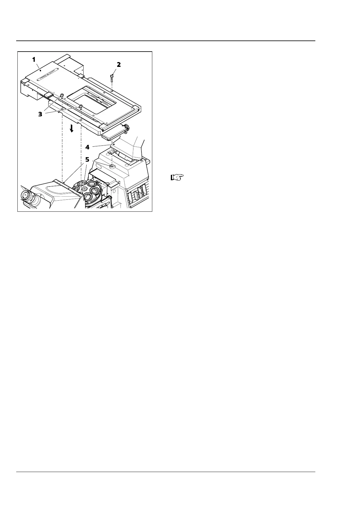
4.9.4 Fitting the scanning stage 130x85
MAT; CAN
Scanning stage 130x100 MAT; CAN rests directly
on three contact points which have drilled screw
holes for fastening.
• To improve access during stage assembly, the
carrier for transmitted-light illumination
(Fig. 27/4) (if fitted) can be tilted backwards.
• Place scanning stage 130x100 MAT; CAN
(Fig. 27/1) on the three contact points
(Fig. 27/5) of the stand and fix it in position
using three Allen screws (two at the front
(Fig. 27/3), one at the rear (Fig. 27/2)).
All stands and stages are supplied with
appropriate spacer disks.
Spacer disks of 4 mm or 6
mm are
necessary when using recessed
mounting frames.
If using flat mounting frames which are
flush to the stage (e.g. 451344) and
160x110 stage pinhole apertures (e.g.
451345-
9902) do not use spacer disks
(in case of mechanical and scanning
stages)!
Fig. 27 Fitting the scanning stage 130x100