OPERATION
ZEISS Illumination and contrast techniques Axio Observer
166 431004-7244-001 12/2016
5.12.10 Setting up reflected light TIC
(1) Application
The reflected-light TIC technique (microinterferometry; TIC = Total Interference Contrast in circularly
polarized light) can be used to image and measure object structures available in different azimuths.
(2) Instrument equipment
− Axio Observer materials with attached microLED
or adjusted HAL 100 illuminator
− EC Epiplan-Neofluar or Epiplan objectives with
additional designation "DIC" or "Pol".
− 6x20 TIC slider with accompanying C-DIC P&C
reflector module.
(3) Setting reflected light TIC
• Place the specimen (e.g. a step-shaped object)
on the stage and prepare the microscope as
described in section 5.12.5 for reflected light
brightfield.
• Swivel in the C-DIC/TIC P&C reflector module
on he reflector turret (Fig. 154/7) into the beam
path.
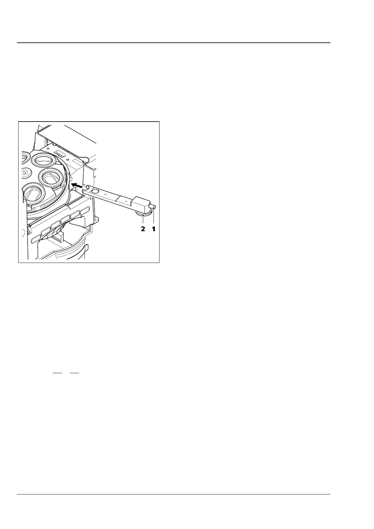
• Insert TIC slider 6x20 (see Fig. 159) into the slot
below the nosepiece. In the field of view,
colored interference fringes appear.
• To select the structure to be measured, turn selector wheel (Fig. 159/2) of TIC slider or modulator
turret until the interference fringe pattern is vertical to the splitting direction of the specimen. Use the
adjusting screw (Fig. 159/1) of the TIC slider to shift the interference fringes.
The step height is then determined using to the following formula:
where: d = step height in nm
n = refractive index of the environment, usually air (n = 1)
∆ = path difference
a = spacing of interference fringes
b = offset of interference fringes at the step
λ = wavelength of the illumination in nm
Fig. 159 TIC slider 6x20