78-9000-5020-0 Rev C 41
12. Locating Buried Sheath Faults and Earth Return
Faults (3M
™
Dynatel
™
Locator Models 7573 only)
Note: Remove both the near-end and far-end grounding from the test section.
A. Transmitter Setup
Note: Do not make any connections while the transmitter is on.
Step 1. Attach the red clip to the earth-faulted conductor of the cable or conductor
under test.
Step 2. Place the ground rod behind the transmitter and in parallel with the target path..
Step 3. Connect the black clip to the ground rod behind the transmitter.
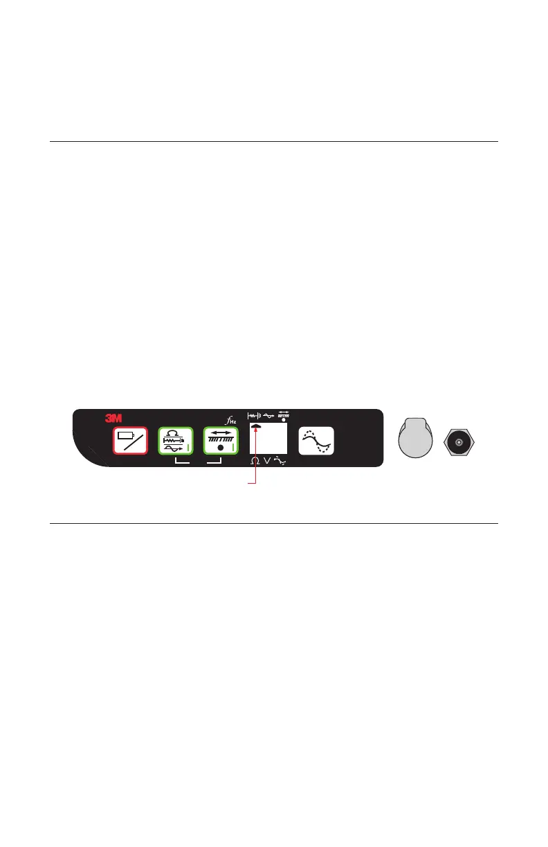
Step 4. Press and hold On/Off [T-1] to perform a battery test.
Step 5. Press on [T-2] once to power on the transmitter. This will place the transmitter
in Ohm-meter mode. An Indicator Flag will be displayed above the ohm
symbol, Ω, in the Digital Display [T-4].
− The resistance of the fault will be displayed in ohms on the transmitter
Digital Display [T-4].
Step 6. Press on [T-2] again, to select Fault mode.
− An Indicator Flag will be displayed above the fault locating symbol in the
Digital Display [T-4].
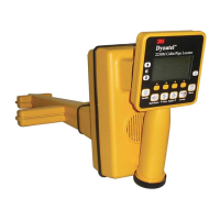
off
+
-
o
Trace
on
on
Output Level
Dynatel
TM
7573
Flag
B. Pinpointing the Buried Fault
Step 1. Connect the 3M
™
Earth Contact Frame to the External Jack [10] of the receiver
using the Earth Contact Frame cable.
Step 2. Press On/Off [2] to power on the receiver.
Step 3. Press Menu/OK [6].
Step 4. Press Fault [SK] to select Fault mode. The receiver display screen will display
"Fault Calibrating" for about 5 seconds.
Step 5. Hold the receiver in one hand and the Earth Contact Frame in the other with the
solid green-banded leg of the frame toward the test section. Near the location of
the ground rod (about one Earth Contact Frame width away), insert the Earth
Contact Frame probes fully into the ground in line with the target path.
Step 6. Press REF [SK] to record the fault Signal Strength level reference. The signal
level will be recorded in the box above REF [SK] on the display. This reference
indicates the Signal Strength [15] level at the ground rod. When the operator
reaches the major fault location, the Signal Strength [15] indicated on the
receiver will be very close (within 12dB) to this reference signal strength level.
 Loading...