Operation Manual / 4 Product description / A100-M axial
9 Taking a turbocharger out of operation / 9.2 Locking the rotor
© Copyright 2019 ABB. All rights reserved. HZTL4033_DE Revision C February 2019
9.2.2 Fitting the locking device
CAUTION
Turbocharger damage resulting from rotor unbalance
Removing the balancing screws from the compressor wheel will result in ro-
tor unbalance.
u Only use free threaded holes to fit the lifting spigot (74027).
u Remove filter silencer or air suction branch (see chapter entitled Removing / Installing air-
inlets →59).
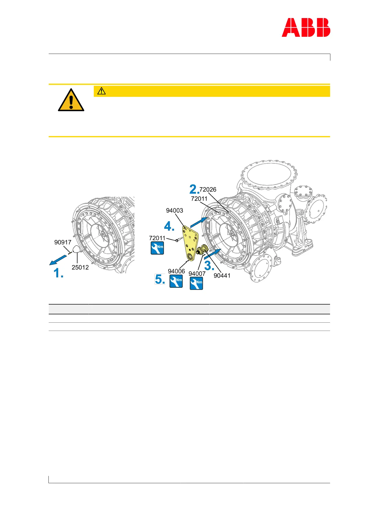
Fig.64: Fitting the locking device
Product Part number 72011 Part number 94006 / 94007
A170-M 170 Nm 25 Nm
A175-M 220 Nm 50 Nm
Table47: Locking device tightening torque
1. Press off the spinner nose cone (25012) with the press-off screw (90917).
2. Remove two studs (72026) and three screws (72011) in the upper area.
3. Insert the lifting spigot (90441) into the compressor wheel.
Screw bolts (94007) into the free threaded holes of the compressor wheel.
4. Position assembly/disassembly device (94003) with bolts (72011) and lifting spigot
(90427).
Rotate compressor wheel in such a way that the holes in the lifting spigot (90427) corres-
pond with the holes in the assembly/disassembly device (94003).
5. Secure assembly/disassembly device (94003) to the lifting spigot (90427) with bolts
(94006).
Page 95 / 108
 Loading...